What Is a Three Way Valve and How Does It Work?
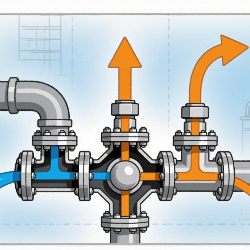
A three way valve is a compact control device that directs, mixes, or separates fluid through three connected ports. It appears in hydronic heating, cooling systems, process equipment, and industrial pipelines. Inside the body, a rotating ball, plug, or movable stem changes the flow path. One port may receive water, while the other two distribute it toward different circuits. In another arrangement, two streams combine before leaving through a common outlet.
Understanding the valve requires more than memorizing port labels. The valve’s design, flow direction, pressure rating, temperature range, and actuator type all affect performance. A technician may hear a faint whistling sound when the valve is partly closed. That sound can indicate excessive pressure loss, incorrect sizing, or unstable flow. It is small. The effect may not be. Manual handles suit simple systems, while electric or pneumatic actuators support automatic temperature and pressure control. Control signals must match the actuator and the wider system.
This guide explains how a three way valve works in practical terms. It examines common valve configurations, internal movement, operating modes, installation details, and typical applications. Reliable selection begins with accurate system information, including media type, pipe size, required flow rate, and operating pressure. Manufacturers’ technical data should guide final decisions. Real installations can differ from diagrams. That point deserves attention. A valve that looks correct on paper may still perform poorly if installed backward, undersized, or poorly supported. Understanding these limitations helps engineers, technicians, and maintenance teams make safer, more dependable choices.
What Is a Three-Way Valve?
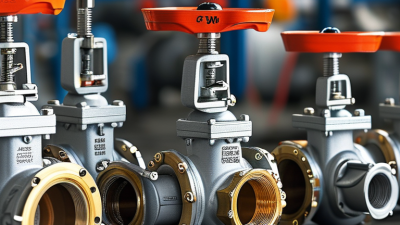
A three-way valve is a flow-control device with three connected ports. It directs, mixes, or separates fluids inside a piping system. Unlike a two-way valve, it can manage two flow paths at the same time. Common designs include L-port and T-port configurations. Their internal passages determine how fluid moves between the ports.
A three-way valve may mix hot and cold water before it reaches a heating circuit. It may also divert flow from one pipe to another. An actuator, handle, or control signal turns the internal plug or ball. This movement changes the open passages and controls the flow direction. In practical inspections, technicians check the valve body, connections, and actuator response. A stiff handle, uneven temperature, or faint dripping can indicate trouble. The simple explanation is useful, but incomplete. Pressure, fluid temperature, valve position, and port design all affect performance.
Tips: Confirm the port markings before installation. Do not assume every three-way valve works the same way. Test the flow path slowly and watch for leaks. Keep the valve accessible for maintenance. If the system behaves strangely, review the control signal and piping layout before replacing parts. A small installation error can create a large circulation problem.
What Is a Three-Way Valve and How Does It Work?
A three-way valve regulates fluid by combining two inlet streams into one outlet or diverting one inlet stream toward two outlets. This chart shows the ideal mixed-water temperature when hot water at 80°C is blended with cold water at 20°C. The values assume steady flow, equal heat capacity, and negligible heat loss.
How a Three-Way Valve Controls Fluid Flow
What Is a Three-Way Valve and How Does It Work?
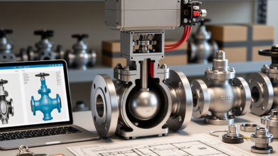
A three-way valve controls fluid flow through three connected ports. Its internal plug or ball redirects, mixes, or divides the fluid. In a mixing arrangement, two inlet streams combine before leaving through one outlet. In a diverting arrangement, one inlet moves toward either outlet. A quarter-turn actuator may rotate the valve, while a linear actuator may lift its control element. Small movements matter. A two-degree change can alter flow balance in a sensitive heating loop.
Control systems use temperature, pressure, or flow sensors to adjust the valve position. For example, a sensor detects cold return water in a hydronic circuit. The actuator then opens the warmer supply path and reduces bypass flow. This maintains a target temperature without constantly running the pump at full output. The International Energy Agency reported that buildings consumed about 30% of global final energy in 2022. Better fluid control can support efficiency, although the valve alone cannot solve poor system design.
Sizing remains critical. An oversized valve may operate near its seat, causing unstable control and audible movement. An undersized valve can create excessive pressure loss. The U.S. Department of Energy recommends checking control settings, sensor placement, and system balancing together. Real installations are less perfect than diagrams suggest. Dirt, air pockets, and delayed sensors can make a correctly installed valve respond poorly. Regular inspection of strainers, actuator travel, and temperature readings is therefore practical, not optional.
The Main Types and Configurations of Three-Way Valves
A three-way valve controls fluid through three connected ports. Its body can mix two inlet streams or divide one inlet stream into two outlets. The main configurations are mixing and diverting. In a mixing arrangement, hot and cold water enter separately, then leave through one common port. In a diverting arrangement, one supply enters and splits toward different circuits. Two paths meet. This difference affects temperature control, pressure balance, and actuator movement.
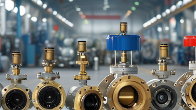
Port design also changes the valve’s behavior. A T-port valve can connect several passages at once, making it useful for mixing or continuous flow control. An L-port valve usually connects two passages at a time. It often suits simple flow switching. Three-way globe valves provide steady modulation and accurate throttling. Rotary ball or plug valves move quickly and create compact installations. However, fast movement is not automatically better. A rapid stroke can cause water hammer or unstable temperature changes.
Selection should match the system’s real operating conditions. Check the medium, pressure, temperature, flow direction, and required leakage class. A technician should also confirm whether the valve must control flow or only isolate a circuit. The actuator’s fail position deserves attention during power loss. A valve sized only by pipe diameter may perform poorly. Oversizing can cause hunting, while undersizing creates excessive pressure loss. The choice is not always obvious; field measurements sometimes challenge the original design drawing. During commissioning, verify each port physically, because labels and assumed flow paths can be misunderstood.
Key Components and Operating Mechanisms
A three-way valve directs one fluid stream toward two outlets, or combines two streams into one. Its key parts include the valve body, three ports, trim, stem, actuator, and seals. The body holds pressure. The trim controls the opening. The actuator moves the stem after receiving a manual, pneumatic, or electric signal.
There are two common operating patterns: mixing and diverting. In mixing service, ports A and B combine at port AB. In diverting service, port AB flows toward A or B. A rotary plug turns inside the body, while a linear stem lifts or lowers a disc. Small movement can change flow significantly. That detail is easy to underestimate.
Correct sizing matters. The U.S. Department of Energy reports that pumping systems can consume 25%–50% of electricity in some industrial plants. A poorly selected valve may increase pressure loss and operating costs. It may also create unstable temperature control. ASHRAE guidance stresses proper valve authority and system balancing for reliable hydronic control.
Field technicians usually inspect the actuator, stem alignment, seals, and port markings together. A clean schematic is not enough. Dirt, air pockets, or incorrect flow direction can defeat a sound design. I would also question oversized valves, because they often operate near the closed position. That causes hunting, noise, and uneven control. The mistake is common.
Common Applications and Selection Considerations
A three-way valve controls fluid direction, temperature, or flow rate through three ports. It can mix two streams into one outlet or divert one stream between two outlets. An actuator moves the plug or ball after receiving a signal from a controller. The valve responds continuously, not magically. Poor calibration still causes unstable temperatures.
Applications
Common applications include chilled-water coils, hot-water heating loops, district-energy substations, and process cooling systems. In a mixing circuit, the valve blends return water with supply water. This protects equipment from thermal shock and improves temperature control. The International Energy Agency’s 2023 Global Status Report for Buildings and Construction reported that buildings used about 30% of global final energy in 2022. Better hydronic control can reduce avoidable pumping and heating losses, although valve performance depends on the whole system.
Selection requires more than matching pipe size.
Engineers should check flow rate, pressure drop, temperature range, fluid chemistry, port configuration, and actuator torque. The required flow coefficient, or Cv, must suit the operating point. Oversized valves often hunt near closed positions. Undersized valves create excessive pressure loss. Consider leakage class, fail-safe position, control signal, and maintenance access. ASHRAE’s HVAC guidance emphasizes system balancing and control stability, yet field conditions are often less tidy than design drawings. Dirt, air, and incorrect sensors can defeat a technically suitable valve. Test the installed assembly under real load.