Print Logo

2026 Best Relief Valve Types for Industrial Buyers

Industrial buyers rarely choose a relief valve by size alone. The right device must match the pressure scenario, process fluid, temperature, and discharge conditions. A mismatch can mean unstable operation, unwanted leakage, or inadequate protection. Small details matter.

The market context is substantial, though not specific to relief valves. Grand View Research estimated the global industrial valves market at about USD 77.8 billion in 2023. That broad estimate reflects the scale of valve procurement, not the size of the relief-valve segment. For pressure-relief selection, buyers should consult recognized engineering references, including API Standard 520 for sizing and selection and API Standard 521 for pressure-relieving and depressuring systems. Applicable codes and qualified engineering review remain essential; a product-page rating alone is not a design basis.

This guide compares spring-loaded, pilot-operated, and other common relief valve types for industrial applications. It highlights where each design can fit, what operating limits deserve scrutiny, and which questions to ask suppliers. Check set pressure, required capacity, backpressure, materials, and maintenance access before comparing quotations. A valve that performs well on a clean utility line may behave differently with viscous, corrosive, or fluctuating process media. No valve is perfect. Real systems are messier than selection tables suggest, so confirm assumptions against actual operating conditions and documented engineering calculations.
2026 Best Relief Valve Types for Industrial Buyers

What a Relief Valve Is and Its Role in Industrial Systems

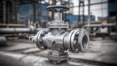
A relief valve is a pressure-protection device installed on equipment such as pumps, heat exchangers, and process vessels. Its job is to open when pressure reaches a defined limit, releasing fluid or gas from the protected section. That is the job. When pressure falls, many designs close again, helping the system return to operation. The valve does not prevent every pressure rise; it provides a controlled escape path.

Industrial systems use different designs. Spring-loaded valves are common in straightforward services, while pilot-operated designs can suit larger flows or tighter operating ranges. The choice depends on the medium, temperature, required capacity, and pressure conditions at the outlet. A valve selected for clean air may not behave well with sticky, corrosive, or particle-filled fluids. Small details matter.

Buyers should check the set pressure, rated relieving capacity, materials, and discharge arrangement against the equipment data. The outlet matters: a narrow or pressurized discharge line can affect performance. That point is easy to miss on a drawing. Sizing also deserves careful review; a valve that looks substantial may still lack capacity for a credible overpressure event. Maintenance records, inspection access, and operating history help confirm whether the chosen valve remains suitable. No single type fits every plant.
How Relief Valves Detect and Control Excess Pressure

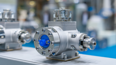
A relief valve responds to pressure at its inlet, not to a general sense that a system is working too hard. In a spring-loaded design, process pressure pushes a disc or poppet against a calibrated spring. When the set pressure is reached, that force overcomes the spring and the valve opens. Some designs open sharply; others lift more gradually. That difference matters.

Pilot-operated valves use a smaller pilot mechanism to sense pressure and control a larger main valve. They can suit demanding flow conditions, but small sensing passages need clean, compatible process fluid. A blocked line can delay the response. It is an easy detail to overlook.

Opening the valve is only part of pressure control. The outlet piping must carry discharged fluid without excessive backpressure, which can affect opening and reseating. Buyers should check set pressure, required relieving capacity, temperature, fluid properties, and allowable backpressure against the system data. Field conditions may differ from a test bench. A valve that meets its specification can still perform poorly if installed incorrectly, so qualified sizing and installation review matter.

2026 Best Relief Valve Types for Industrial Buyers

How relief valves detect and control excess pressure

Illustrative gas or vapor example: normal operating pressure is shown at 90% of set pressure, with relieving pressure at 110% (10% overpressure). Actual operating margins and allowable overpressure depend on the applicable code, service conditions, and certified valve design.

A spring-loaded relief valve opens when inlet pressure overcomes its spring force. A pilot-operated valve uses a pilot to sense pressure and control the main valve. Balanced-bellows designs help reduce the effect of backpressure. Select the valve type based on the fluid, required capacity, backpressure, operating conditions, and applicable regulations.

Major Relief Valve Types and Their Operating Principles

A spring-loaded relief valve opens when inlet pressure overcomes the force of its preset spring. As pressure rises, the disc lifts from its seat and releases fluid through the outlet. When pressure falls, the spring pushes the disc closed, though a small pressure drop may be needed for reseating. Simple, but not universal. These valves are common in straightforward systems, but flow capacity and back pressure still matter.

A pilot-operated valve uses a smaller pilot to sense pressure and control a larger main valve. This design can handle high capacities with less pressure buildup, but small pilot passages may be affected by dirty fluids. Real installations are messier than diagrams. Balanced-bellows designs use a flexible bellows to reduce the effect of outlet back pressure on the set point; they do not remove every installation concern. Thermal relief valves address a different case: liquid trapped between closed valves can expand as it warms, so a small valve releases that pressure. Selection depends on fluid, temperature, required capacity, and piping conditions. Check the expected back pressure, too. A valve that looks suitable on a drawing may behave differently once connected to the actual system.

2026 Best Relief Valve Types for Industrial Buyers — Major Relief Valve Types and Their Operating Principles
Relief Valve Type Operating Principle Common Applications Key Advantages Selection Considerations
Conventional Spring-Loaded Safety Valve A spring holds the disc against the seat. When inlet pressure reaches the set pressure, the force on the disc overcomes the spring force and the valve opens. It recloses as pressure falls. Steam, gas, vapor, and compatible liquid services where outlet pressure is close to atmospheric or remains relatively stable. Simple construction, no external pilot system, and straightforward inspection and maintenance. Built-up backpressure at the outlet can affect set pressure and capacity. Check allowable backpressure and the applicable code requirements.
Balanced-Bellows Safety Valve A bellows isolates the spring and bonnet area from outlet pressure, reducing the effect of backpressure on the valve’s opening characteristics. Systems with variable or significant superimposed backpressure, including some process and flare-header services. Helps maintain more consistent operation when outlet pressure varies; the bellows can also limit contact between process fluid and spring components. Bellows condition and venting need attention. Confirm the design’s allowable backpressure and suitability for the fluid and operating environment.
Pilot-Operated Pressure Relief Valve A pilot senses system pressure and controls pressure in the main valve’s dome. The main valve is held closed during normal operation and opens when the pilot signals at the set pressure. High-pressure gas service, large-capacity systems, and applications requiring tight operation near the set pressure. Can provide low leakage close to set pressure and a high capacity relative to connection size in suitable designs. Check pilot compatibility with the fluid, minimum operating pressure, sensing-line arrangement, contamination risk, and response requirements.
Direct-Acting Pressure Relief Valve In liquid service, process pressure acts directly on the valve element and overcomes a spring force to open the flow path. The valve modulates to limit pressure. Hydraulic systems, pumps, and liquid process lines requiring protection from excess pressure. Compact, self-contained, and suitable for local pressure control without a separate pilot circuit. Relief valves for liquid service are not interchangeable with safety valves intended for compressible fluids. Evaluate flow capacity, pressure drop, and fluid compatibility.
Thermal Relief Valve A small direct-acting valve opens when liquid pressure rises above its set point, often because trapped liquid expands as temperature increases. Blocked-in liquid sections of piping, small-bore lines, and equipment where thermal expansion can create excess pressure. Provides a simple means of relieving thermal expansion pressure in a confined liquid volume. Size for the credible thermal expansion scenario and route discharge to a safe location. It is not a substitute for a process overpressure protection device.
Balanced-Piston Relief Valve A piston arrangement balances or reduces the influence of outlet pressure on the pressure acting on the valve element, depending on the specific design. Selected process and liquid services where backpressure effects or a particular pressure-control arrangement must be addressed. May reduce sensitivity to backpressure compared with an unbalanced direct-acting design. Design details vary. Verify the manufacturer’s pressure-balancing method, flow characteristics, fluid suitability, and applicable certification.
Rupture Disc (Non-reclosing Device) A calibrated membrane bursts at its specified differential pressure, opening a flow path. It does not automatically reseal after activation. Corrosive, viscous, or fouling services; rapid pressure-rise scenarios; and installations where a non-reclosing device is specified. No moving parts and a direct, full-opening action after rupture; materials can be selected for challenging process fluids. Requires replacement after activation. Consider temperature effects, burst tolerance, fragment control, and whether a relief valve or combination arrangement is required.

How to Choose a Relief Valve for an Industrial Application

2026 Best Relief Valve Types for Industrial Buyers

How to Choose a Relief Valve for an Industrial Application

Choosing a relief valve starts with the hazard, not the catalog. Confirm the protected equipment’s maximum allowable working pressure, required relieving capacity, fluid phase, temperature, and discharge conditions. Clean steam, flashing liquid, and compressible gas behave differently. A conventional spring-loaded valve may suit low, stable backpressure; a balanced-bellows design can help where outlet pressure varies. Pilot-operated valves may fit applications needing tight operation near set pressure, but contamination and maintenance access matter.

Small details matter.

Use documented process data, including credible blocked-outlet, thermal-expansion, and fire scenarios, rather than normal operating flow alone. API 520 Part I gives 10% overpressure as a common sizing basis for many single-valve, non-fire cases; the applicable code and scenario can change that basis. ASME BPVC Section XIII also provides requirements for pressure-relief devices. Treat these figures as design criteria, not universal settings. Check inlet pressure loss, built-up backpressure, materials, and safe discharge routing with a qualified engineer. In practice, a neat spreadsheet can still miss a sticky fluid or a long, undersized outlet line. Revisit assumptions against field conditions and maintenance history before approving the selection.

Installation, Inspection, and Maintenance Considerations

Installation quality often determines whether a relief valve performs as intended. Mount it in the orientation specified for its design, with a short, adequately sized inlet and minimal pressure loss. A long, narrow inlet can cause chatter or reduce capacity. Keep the valve accessible, and support discharge piping independently so its weight does not load the outlet. Route discharge to a safe, visible location, accounting for temperature, fluid hazards, drainage, and backpressure. Details vary by service.

Before commissioning, verify the nameplate set pressure, materials, and capacity against the protected equipment and approved design data. Check that shipping restraints are removed and that isolation arrangements cannot accidentally block protection. Inspect for corrosion, deposits, leakage, damaged seals, loose supports, and signs of vibration. Record findings, not just pass or fail. Maintenance intervals should reflect the fluid, operating cycles, and service history; a dirty process may need closer attention than clean air. Bench testing or adjustment belongs with qualified personnel using calibrated equipment and documented procedures. Even a careful checklist can miss a changing process condition. Revisit assumptions after modifications.