What Are the Top Types of Relief Valves?
Choosing the right relief valve begins with understanding the hazard, not memorizing product names. Pressure can rise quietly inside a boiler, pipeline, storage vessel, or chemical reactor. Then, within seconds, a weak component may fail. A properly selected relief valve opens at a controlled pressure. It releases excess fluid. It helps protect equipment, operators, and surrounding facilities.
Dr. Hans D. Baumann, a respected valve engineer, expressed a practical principle: “A valve is only as good as its application.” That idea matters here. Spring-loaded safety valves suit many general pressure systems. Pilot-operated relief valves can handle higher pressures and larger flow rates. Vacuum relief valves protect tanks from collapse during draining or cooling. Rupture discs respond quickly and contain no moving parts. Some systems combine a rupture disc with a relief valve for added protection.
This guide compares the top types of relief valve and explains where each design performs best. It considers set pressure, temperature, fluid condition, discharge capacity, maintenance, and installation space. Standards such as ASME and API also influence responsible selection. Still, standards do not replace engineering judgment. A valve that works well on clean steam may struggle with sticky chemicals or abrasive particles. That detail is easy to overlook.
Real applications are rarely perfect. Pressure readings may drift. Maintenance records may be incomplete. Operators may misunderstand the discharge path. Therefore, the safest choice requires verified process data, competent review, and regular testing. The goal is not simply opening at the right number. It is dependable protection when the process behaves badly.
Spring-Loaded Pressure Relief Valves: Design, Operation, and Uses
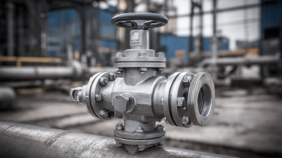
Spring-loaded pressure relief valves protect pressurized equipment from dangerous overpressure. Their design is direct. A spring presses a disc against the valve seat. When system pressure exceeds the set pressure, the disc lifts and releases fluid through the outlet. As pressure falls, the spring pushes the disc back into position.
The valve’s performance depends on more than its set pressure. Temperature, fluid type, back pressure, and discharge capacity all affect reliable operation. In boilers, storage vessels, compressors, and process piping, engineers select materials that match the service conditions. A valve may look clean outside but still have corrosion, deposits, or a damaged seat inside. That detail is easy to miss. Incorrect sizing can cause chatter, leakage, or slow pressure release. Regular inspection and controlled testing help confirm the valve opens and reseats correctly. However, test results should be reviewed by qualified personnel and compared with the equipment’s design requirements.
Tips:
Check the nameplate and set pressure before maintenance. Keep outlet piping supported and unobstructed. Inspect for vibration, corrosion, and visible leakage. Do not adjust the spring without approved procedures. Record each test, even when the valve appears normal. Simple records often reveal gradual performance changes.
Pilot-Operated Relief Valves: Design, Operation, and Uses
What Are the Top Types of Relief Valves?
Pilot-Operated Relief Valves: Design, Operation, and Uses
Relief valves protect pressurized equipment from dangerous overpressure. Common designs include spring-loaded, pilot-operated, vacuum, and rupture-based devices. Pilot-operated relief valves are especially useful in large process vessels, pipelines, and systems requiring precise pressure control.
A pilot-operated relief valve uses a small pilot valve to sense system pressure. When pressure reaches the set point, the pilot changes position and releases pressure from the main valve dome. Pressure then lifts the main piston, opening a larger flow path. This design can provide tighter sealing and lower blowdown than many conventional spring-loaded valves. It also performs well under high pressure. However, the pilot circuit needs clean, compatible fluid. Blocked sensing lines can delay response. That risk is easy to underestimate.
Tips: Confirm the set pressure, temperature range, and discharge capacity before installation. Inspect pilot filters and sensing lines during maintenance. Keep the valve accessible for testing. A technician should also check for vibration, corrosion, and unusual pressure cycling. Small details matter. Field conditions can expose weaknesses that calculations miss. When selecting a valve, engineers should review operating history, not only design data. A stable system may still experience rapid pressure spikes during startup or shutdown. No design is perfect. Reliability improves when testing, documentation, and practical inspection support the original engineering judgment.
Safety and Safety Relief Valves: Key Differences and Applications
What Are the Top Types of Relief Valves?
Safety valves and safety relief valves both protect equipment from dangerous pressure buildup. However, their operating behavior is different. A safety valve usually opens rapidly at a preset pressure. This “pop” action suits steam, air, and other compressible fluids. It quickly releases pressure from boilers, pipelines, and pressurized vessels. A safety relief valve can open quickly or gradually. Its response depends on pressure conditions and valve design. This makes it suitable for gas, steam, and liquid service.
The difference matters during equipment selection. Liquid systems often require controlled, modulating discharge. Gas systems may need rapid pressure release. Engineers should check set pressure, allowable overpressure, temperature, back pressure, and discharge capacity. Incorrect sizing can leave pressure trapped inside the vessel. Installation details matter too. Poorly designed outlet piping may restrict flow or create harmful back pressure. In field inspections, small errors often become serious.
Tips:
Read the equipment datasheet carefully. Confirm the fluid and operating temperature. Keep discharge lines supported and unobstructed. Schedule regular inspection and testing. Never assume one valve suits every application. A simple rule can mislead. Actual process conditions decide the safer choice. When conditions change, valve performance should be reviewed again.
Thermal Relief Valves: Protection Against Heat-Driven Pressure Rise
Thermal relief valves protect closed, liquid-filled sections from pressure caused by rising temperature. When sunlight, steam, or nearby hot surfaces warm trapped fluid, pressure can rise surprisingly fast. Liquids expand little visibly, yet their pressure response can be severe. A small valve may prevent a large failure. In practice, the valve is installed between isolation points, often on piping, jackets, filters, or pump discharge sections. It opens at a controlled set pressure. It then releases limited fluid to a safe return or collection point. Keep the path open.
Correct selection requires more than matching pipe size. Engineers review fluid compatibility, operating temperature, set pressure, relieving capacity, and discharge routing. Stainless steel may suit one process, while seals may weaken under heat or chemicals. The valve should remain accessible for inspection. Its outlet should never face personnel or create a slip hazard. During maintenance, technicians check corrosion, blockage, leakage, and actual set pressure. A relief valve is not a substitute for sound isolation procedures. It may also be overlooked when a line appears inactive. That assumption can be wrong. Thermal cycling can loosen connections and alter performance over time. Documented testing supports dependable protection, although unusual heat sources and changing fluids deserve another review before commissioning.
Vacuum Relief Valves: Preventing Tank Collapse and Vacuum Damage
Vacuum relief valves protect atmospheric storage tanks from collapse when internal pressure falls below ambient pressure. This condition can occur during rapid liquid withdrawal, steam condensation, cooling after filling, or a blocked normal vent. The danger is quiet. A tank may buckle before operators notice visible deformation.
API 2000 and ISO 28300 provide widely used guidance for sizing emergency and normal venting systems. Their calculation methods consider liquid flow, vapor generation, temperature change, and atmospheric conditions. For perspective, a 10-meter-diameter tank exposed to only 2 kilopascals of external pressure experiences approximately 157 kilonewtons of compressive force across its roof area. That load can distort thin steel structures quickly. Small valves matter.
A Grand View Research market report estimated the global pressure relief valve market at approximately USD 4.7 billion in 2023. That figure reflects broad industrial demand, not proof of correct installation. Field inspections often find undersized vents, frozen valve seats, or discharge paths obstructed by paint and debris. Maintenance teams should verify set pressure, flow capacity, vacuum tightness, and atmospheric discharge conditions. Testing should match the service fluid and operating temperature. One overlooked detail remains common: a valve can be correctly selected but poorly installed. Tank nozzles, piping losses, and isolation devices can reduce its real performance. Design assumptions deserve another look.