
Print Logo

Top 10 Thermocouple Module Types for Industrial Buyers

Industrial buyers rarely choose a Thermocouple Module by channel count alone. They also need to consider sensor compatibility, isolation, accuracy, response time, and the conditions inside the control cabinet. A module facing vibration, electrical noise, or wide temperature swings may need different protection than one monitoring a stable process line. Small details matter.

NIST Monograph 175, co-authored by M. G. Burns, is a respected reference on thermocouple temperature measurements. A buyer’s principle inspired by that metrology work—not a verified quotation from Burns—is: “Trust the measurement only after checking the sensor, wiring, and reference junction.” That distinction matters. A polished specification cannot compensate for poor installation or mismatched thermocouple types.

This guide compares ten common module types, from compact PLC and remote I/O modules to isolated, high-density, and specialty options. It focuses on practical selection criteria, including input range, cold-junction compensation, channel-to-channel isolation, and integration with existing controllers. Look closely at the datasheet. Check the wiring diagram. Then compare performance under your actual operating conditions, not just ideal laboratory figures. No shortlist is perfect; the right choice depends on the process, the environment, and the cost of a bad reading. Even experienced teams can overlook a grounding detail. That happens. A careful comparison helps buyers ask better questions before purchase.
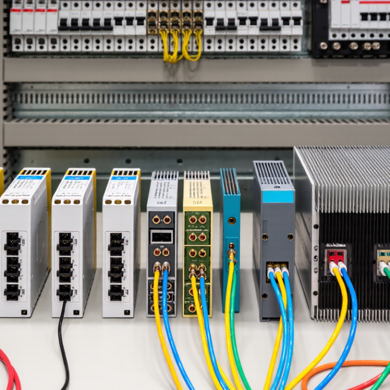
Top 10 Thermocouple Module Types for Industrial Buyers

Thermocouple Modules: Millivolt Inputs, CJC, and IEC 60584-1

Thermocouple modules measure small voltages, not temperature directly. A Type K probe produces roughly 41 µV/°C near room temperature. A 1°C error is only about 41 µV. That signal is vulnerable to electrical noise and poor connections. NIST Monograph 175 documents reference functions and tables for thermocouple types. It offers a useful cross-check, but cannot replace checking the installed sensor.

Cold-junction compensation (CJC) estimates terminal temperature and adds its equivalent thermocouple voltage. The terminal block matters. Keep its copper terminals close together, shield them from drafts, and avoid placing a warm relay beside the reference sensor. Even a precise millivolt input can report biased temperatures if its CJC sensor measures a different thermal zone. Small errors matter.

IEC 60584-1:2013 defines thermocouple reference tables and tolerance classes. For Type K Class 1, tolerance is ±1.5°C or ±0.004|t|, whichever is greater. That is sensor tolerance, not total system accuracy. Buyers should compare input range, resolution, isolation, CJC accuracy, and open-sensor detection. A finer display step does not guarantee a better measurement. Verify the complete loop against a traceable reference at operating temperatures; field gradients can reveal weaknesses that a bench test misses.

Classify 10 Module Designs by Channels, Isolation, Mounting, and Bus

Thermocouple modules are best compared across four practical axes: channel count, isolation, mounting, and bus. Type 1 is a two-channel compact unit for a furnace zone and reference point. Type 2 offers four to eight channels for multi-point skids. Type 3 isolates each channel to reduce ground-loop effects. Type 4 isolates channel banks, trading cost for simpler wiring. Type 5 uses a shared ground for straightforward cabinet layouts. The distinction matters.

Type 6 mounts on a DIN rail beside a controller; Type 7 fits a panel cutout, where front access can ease maintenance. Type 8 places conversion near the sensor, shortening thermocouple leads. Type 9 uses USB for bench testing, but may not suit harsh cabinets. Type 10 connects through RS-485 or industrial Ethernet for distributed monitoring. Small panels benefit. Bus labels alone reveal little about timing or diagnostics.

The IEA’s Energy Efficiency 2023 report attributes roughly 37% of global energy consumption to industry, where temperature drift can affect process efficiency. Compare cold-junction compensation and linearization against the thermocouple tolerances in ASTM E230/E230M; input resolution alone does not guarantee accuracy. A neat taxonomy can mislead. Isolation ratings, common-mode limits, and terminal temperature behavior still matter near motor drives. Check these specifications at operating temperature, not only on paper.

Match K, J, T, E, N, R, S, and B Inputs to Process Temperatures

Choosing a thermocouple module starts with the process temperature, not the sensor’s popularity. Type K covers many general-purpose applications, while J suits moderate temperatures where its materials and environment are appropriate. Type T is useful for colder processes; E offers higher sensitivity in its operating range. N can be a steadier choice at elevated temperatures. For very hot furnaces, R and S are common options, while B is designed for especially high-temperature work. Actual limits depend on the probe, wire, and applicable specifications.

Small details matter. A module must support the selected thermocouple type, its signal range, and the correct linearization. Check cold-junction compensation, channel isolation, and wiring requirements before ordering. A mismatched input can produce plausible-looking, inaccurate readings. That is easy to miss during commissioning.

Tips: Compare the expected process range with the probe’s rated range, leaving room for startup peaks. Verify polarity and extension-wire type at the terminal block. If temperatures drift, inspect connections and cold-junction conditions before replacing the sensor. A range chart helps, but it is not the whole decision.

Top 10 Thermocouple Module Types for Industrial Buyers - Match K, J, T, E, N, R, S, and B Inputs to Process Temperatures

Thermocouple Type Thermoelement Materials Typical Sensor Temperature Range Common Process Applications Selection Considerations Module Input Requirements
K Chromel–Alumel (NiCr–NiAl) −200 to 1,260°C General-purpose furnaces, heat treatment, kilns, engines, and process piping Broad operating range and widely used. At high temperatures, drift and oxidation can affect long-term accuracy. Type K-compatible input, cold-junction compensation (CJC), and extension wire matched to Type K.
J Iron–Constantan (Fe–CuNi) −210 to 1,200°C Legacy industrial equipment, plastics processing, and moderate-temperature furnaces Iron leg can oxidize, so sustained high-temperature or wet environments may shorten sensor life. Type J linearization and CJC; verify polarity and use Type J extension or compensating cable.
T Copper–Constantan (Cu–CuNi) −250 to 400°C Refrigeration, cryogenic systems, laboratories, and food or pharmaceutical temperature monitoring Good choice for low-temperature measurements; the copper leg limits use at elevated temperatures. Type T-compatible input with CJC; check that the module supports the required sub-zero range.
E Chromel–Constantan (NiCr–CuNi) −200 to 900°C Low-temperature process monitoring, environmental chambers, and moderate-temperature equipment Produces a relatively high thermoelectric output, which can be useful for low-level signal measurement. Type E linearization and CJC; confirm the module’s measurement range and input resolution.
N Nicrosil–Nisil (NiCrSi–NiSi) −200 to 1,300°C High-temperature furnaces, kilns, and applications needing stable performance over time Designed for improved stability compared with Type K in many high-temperature applications; compatibility with existing wiring must be checked. Type N-specific input linearization and CJC; do not substitute Type K extension wire.
R Platinum–13% Rhodium / Platinum (Pt–13%Rh/Pt) 0 to 1,600°C Glass production, high-temperature furnaces, and controlled industrial heat treatment Precious-metal sensor with low output; protect it from contamination and mechanical damage. Type R input, suitable low-level signal resolution, CJC, and compatible compensating cable.
S Platinum–10% Rhodium / Platinum (Pt–10%Rh/Pt) 0 to 1,600°C Laboratory and reference measurements, glass manufacture, and high-temperature process control Offers stable high-temperature measurement when correctly installed, but is costly and vulnerable to contamination. Type S linearization, CJC, and an input capable of accurately resolving the relatively low sensor signal.
B Platinum–30% Rhodium / Platinum–6% Rhodium (Pt–30%Rh/Pt–6%Rh) Approximately 600 to 1,700°C for practical measurement Very high-temperature furnaces, glass tanks, and other hot industrial processes Best suited to high temperatures; its low thermoelectric output makes it less practical at lower temperatures. Type B-specific input and linearization, CJC, and sufficient signal resolution for the intended operating range.
C Tungsten–5% Rhenium / Tungsten–26% Rhenium (W–5%Re/W–26%Re) Approximately 0 to 2,300°C Specialty vacuum, inert-atmosphere, or reducing-atmosphere furnaces Not suitable for oxidizing atmospheres at high temperatures; availability and calibration support may be limited. Confirm that the module explicitly supports Type C or the sensor’s specified calibration; standard K/J/T inputs are not interchangeable.
D Tungsten–3% Rhenium / Tungsten–25% Rhenium (W–3%Re/W–25%Re) Approximately 0 to 2,320°C Specialty ultra-high-temperature measurement in vacuum, inert, or reducing atmospheres Requires a controlled atmosphere at high temperatures and specialized sensor protection and handling. Use a module with Type D-specific support or a verified custom input curve, plus compatible wiring and CJC.

Temperature ranges are typical thermocouple-element limits, not guaranteed operating limits for a complete probe or module. Sheath material, insulation, atmosphere, wiring, calibration, and input-module specifications can reduce the usable range. Confirm the applicable sensor standard and module configuration before selection.

Verify K-Type Class 1 Accuracy: ±1.5°C or ±0.4% (−40 to 1,000°C)

Top 10 Thermocouple Module Types for Industrial Buyers

When checking a K-type module, read the accuracy specification carefully. Class 1 thermocouple tolerance is ±1.5°C or ±0.4% of the measured temperature, whichever is greater, over −40 to 1,000°C. That is the sensor tolerance, not a promise of total measurement accuracy. At 800°C, for example, 0.4% equals 3.2°C. A display showing tenths of a degree does not make the measurement that precise. Small print matters.

The module adds its own sources of error. Cold-junction compensation, input linearization, electrical noise, and terminal temperature can all affect the reading. Check whether the module’s stated accuracy includes these factors, and whether it applies across the full operating temperature range. In commissioning, compare a stable input with a calibrated thermocouple simulator, then inspect readings near both ends of the expected range. Keep extension-wire type and polarity consistent; a reversed pair can produce confusing results. It is easy to overlook connector details.

A practical specification should state the thermocouple class, module accuracy, compensation method, and calibration conditions. Ask for test data, not only a headline figure. Even then, installation conditions may differ from the test bench. That gap deserves attention.

Top 10 Thermocouple Module Types for Industrial Buyers

Verify K-Type Class 1 Accuracy: ±1.5°C or ±0.4% (−40 to 1,000°C)

The chart shows the IEC 60584-2 Class 1 tolerance limit for Type K thermocouple wire: ±1.5°C from −40°C to 375°C, then ±0.4% of the measured temperature from 375°C to 1,000°C. These are sensor tolerance limits, not the total accuracy of a measurement module; module and installation errors may add to them.

Size Sampling and Isolation for 50/60 Hz Plant Noise

Thermocouple signals are small, so nearby motors, heaters, and long cable runs can make plant noise visible in readings. At a furnace cabinet, a temperature trace may show a regular ripple even when the process is steady. Small signals matter. Choose a module with input types that match the installed sensors, plus suitable cold-junction compensation. Channel count matters too: leave room for spare probes rather than forcing a crowded installation later.

Sampling and filtering should address both 50 Hz and 60 Hz interference. A fast enough sampling rate, paired with an appropriate anti-alias filter, helps prevent mains noise from folding into the measured signal. Some modules offer line-frequency rejection; confirm the setting matches the site, and check whether it affects response time. Averaging can smooth readings, but excessive averaging may hide a real temperature change. That trade-off is easy to overlook.

Isolation limits unwanted electrical paths between field wiring, channels, and the control system. Compare channel-to-channel and channel-to-bus isolation specifications, especially when sensors span separate machine zones. Keep thermocouple leads away from motor cables, and use the wiring method specified for the sensor type. During commissioning, compare readings with a trusted reference under normal plant load. I would verify it again when nearby equipment starts; a quiet bench test can miss the actual interference.