
Print Logo

How to Find a Tokimec Equivalent Pump?

A Tokimec Equivalent Pump is not identified by a model number alone. A pump may look right on a workbench and still fail to match the original unit’s displacement, pressure rating, rotation, shaft, mounting, or port layout. In hydraulic service, small differences matter. A mismatched shaft or inlet connection can turn a straightforward replacement into costly downtime.

The U.S. Department of Energy’s Improving Pumping System Performance: A Sourcebook for Industry reports that pumping systems account for nearly 20% of global electricity demand. That figure concerns pumping systems broadly, not Tokimec vane pumps specifically. Still, it highlights why selection should consider operating conditions, not just purchase price. Hydraulic Institute guidance likewise emphasizes evaluating pumps within their systems. Check the machine’s nameplate, fluid type, operating pressure, flow needs, and available space before comparing alternatives.

A careful match starts with evidence. Photograph the nameplate and ports, record the shaft dimensions, and compare the candidate’s technical datasheet with the original pump specifications. Then confirm performance at the machine’s actual operating conditions. Close is not always close enough. One limitation deserves honesty: I could not verify a published quotation from a named specialist specifically about Tokimec-equivalent pumps, so I will not invent one. Use manufacturer documentation and qualified hydraulic-engineering advice to verify the final choice; even a well-researched match should be checked against the equipment in front of you.
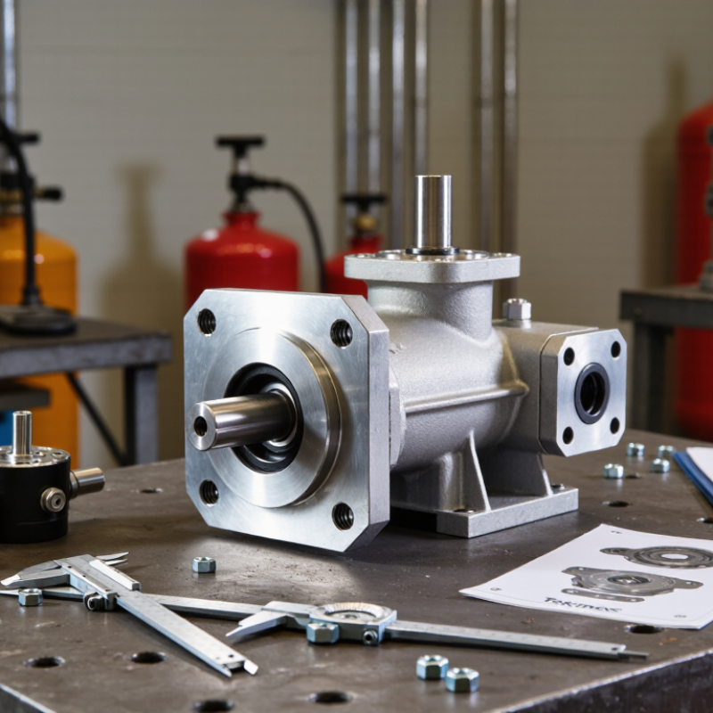
How to Find a Tokimec Equivalent Pump?

Identify the Tokimec Series, Model Code, and Displacement in cm³/rev

To find a suitable equivalent, start with the pump’s series and complete model code. Photograph the nameplate before dirt or fading hides a character. Record every letter and number; similar codes can indicate different shafts, ports, or control options. Then confirm displacement in cm³/rev from the plate or the manufacturer’s technical documentation. Check rotation direction from the drive end, mounting dimensions, shaft type, and port positions. Small detail. Big consequence. A code alone may not reveal a later modification, so compare it with the actual housing.

Displacement also helps check expected flow. A 40 cm³/rev pump turning at 1,500 rpm produces 60 L/min theoretically; real flow is lower because of volumetric losses. The U.S. Department of Energy’s Improving Pumping System Performance: A Sourcebook for Industry reports that pumping systems account for nearly 20% of global electricity demand, and 25–50% of energy use in some industrial facilities. Those figures describe pumping systems broadly, not a specific replacement choice. Use them as context, not proof of compatibility. ISO 4409 sets methods for testing and presenting steady-state performance, so compare documented performance curves where available. I would not trust a displacement match alone. That shortcut can miss a critical control or mounting difference.

Match Rated Pressure, Speed, Flow, and Rotation Direction to the Original

When selecting an equivalent hydraulic pump, compare the original unit’s rated pressure, shaft speed, flow, and rotation direction. A close-looking housing proves little. ISO 4409:2019 describes steady-state testing for hydraulic pumps, including performance measurements that help make comparisons meaningful. Check whether the stated flow is measured at the same speed and pressure as the original. For example, a 20 cm³/rev pump at 1,500 rpm has a theoretical flow of 30 L/min; real output is lower because of internal leakage. Small mismatch, big trouble.

Tips: Confirm whether rotation is specified from the shaft end or port end. These viewpoints can reverse “clockwise.” Verify continuous and peak pressure separately, then check the nameplate, datasheet, and port layout before ordering.

A pump may deliver the target flow at low pressure but fall short under load. Match the operating point, not just the maximum figures. Also compare speed limits and confirm the replacement can run at the machine’s actual shaft speed. A small speed difference changes flow, while excess pressure can increase heat and wear. Record the original pump’s model data, test conditions, and rotation viewpoint; missing details are easy to overlook, and that is where a seemingly suitable substitute can disappoint.

Check Mounting, Shaft, and Port Interfaces Against SAE J744 or ISO 3019

Finding an equivalent pump starts with its mounting interface, not its displacement alone. Compare the flange dimensions and bolt pattern with the relevant SAE J744 or ISO 3019 configuration. Check the pilot diameter and depth, too. A flange can appear to fit while leaving the pump slightly misaligned. Small differences matter.

Next, measure the shaft extension, diameter, and spline or key details. Confirm the coupling engages fully without bottoming out or excessive play. Then inspect the ports separately: record their thread or flange type, size, position, and sealing method. SAE J744 and ISO 3019 help identify mounting and shaft interfaces; they do not confirm every port connection. Do not guess. Use drawings or measured dimensions, and compare them with the replacement pump’s technical data. If a measurement is uncertain, recheck it. A rushed measurement can look convincing, and that is exactly why it deserves a second look.

How to Find a Tokimec Equivalent Pump? - Check Mounting, Shaft, and Port Interfaces Against SAE J744 or ISO 3019

Interface to Check What to Measure or Identify Reference or Comparison Method Match Requirement
Mounting standard and series Identify the mounting-flange standard, size designation, and dimensional series shown on the pump drawing or equipment documentation. Compare the applicable mounting dimensions with SAE J744 or the relevant ISO 3019 series and edition. Use the same standard and size series, or verify every interface dimension against the manufacturer’s certified drawing. Do not assume that similarly sized SAE and ISO patterns are interchangeable.
Mounting pilot Measure the pilot outside diameter, pilot depth, and the mating recess in the equipment. Compare the pilot and recess dimensions, tolerances, and fit with the applicable standard drawing and pump drawing. The pilot must locate the pump correctly and seat fully without interference or excessive clearance.
Bolt pattern Check the number of mounting bolts, hole or thread size, bolt-circle dimensions, and hole positions. Compare the mounting pattern with the applicable SAE J744 or ISO 3019 configuration. All holes must align, and the specified fasteners must engage correctly. Do not use bolt-hole alignment alone as proof of a compatible mount.
Mounting face and seating depth Check the mounting-face condition, flange thickness, register depth, and clearance to the equipment housing. Use the pump and equipment drawings; confirm the dimensions and tolerances for the selected mounting configuration. The flange must sit flush and the pump must clear adjacent components. Avoid forcing the pump into position with the mounting bolts.
Shaft type and dimensions Identify a keyed, splined, or other specified shaft; measure shaft diameter, extension length, keyway dimensions, or spline details as applicable. Compare the shaft-end configuration and dimensions with the applicable SAE J744 or ISO 3019 shaft specification and the driven equipment. The shaft must match the mating coupling or drive, including its engagement length and permitted fit. A matching diameter alone is not sufficient.
Spline details For a splined shaft, confirm the spline form, tooth count, major and minor dimensions, fit class, and engagement length. Check the relevant standard designation and the pump and coupling drawings; use a suitable spline gauge or qualified measurement method where required. The spline designation and fit must match the mating part. Do not select a spline by tooth count alone.
Rotation and drive direction Confirm the required shaft rotation as viewed from the specified shaft end, along with any drive or installation restrictions. Check the pump nameplate, technical documentation, and system schematic. The replacement must be approved for the required rotation and operating arrangement. Confirm before installation; incorrect rotation can prevent proper operation or cause damage.
Port connection type Identify whether each connection is a flange, straight thread, tapered thread, or another specified port type. For split-flange connections, compare the applicable SAE J518 or ISO 6162 interface. For threaded ports, use the specified port standard and thread designation. Match the connection type, sealing method, and standard. Similar-looking threads or flange parts should not be treated as interchangeable without verification.
Port size and sealing face Record each port designation, flange or thread size, sealing-face dimensions, and the required O-ring or gasket arrangement. Compare with the pump drawing, hose or adapter drawing, and the applicable port-interface standard. The port must accept the intended fitting and seal correctly at the system’s specified operating conditions.
Port position and orientation Check inlet and outlet locations, port spacing, orientation, and available clearance for hoses, fittings, and service access. Compare the port layout with the original installation and the proposed pump’s dimensioned drawing. Ports must connect without forced alignment, hose twist, or interference with the frame and nearby components.
Final drawing verification Record the measured values, units, standard designations, and drawing revisions for the pump and mating equipment. Review a dimensioned manufacturer drawing and confirm any uncertain dimensions with the supplier before ordering. Approve the candidate only when mounting, shaft, and port interfaces all match and the required operating specifications are also suitable.

Note: SAE J744 and ISO 3019 cover pump mounting and shaft interface configurations; port connections are checked against their own applicable standards. Dimensions vary by configuration, so use the exact standard designation and a dimensioned drawing rather than assuming a universal size.

Compare Fluid Viscosity and the Pump’s ISO 4406 Cleanliness-Code Requirement

When comparing a replacement pump, check viscosity at operating temperature—not only the lubricant’s name or grade. ISO 3448 classifies an ISO VG 46 fluid at a nominal 46 mm²/s at 40°C, but a cold start can make it much thicker. Thick fluid may delay inlet filling; thin, hot fluid can increase leakage. Record the actual fluid temperature, expected start-up temperature, and viscosity range required by the pump specification. Then compare those values with the candidate pump’s limits. A matching displacement alone is not enough.

Check cleanliness just as carefully. ISO 4406:2021 codes particle counts at ≥4, ≥6, and ≥14 µm(c). For example, a first-position code of 18 represents 1,300–2,500 particles per millilitre at ≥4 µm(c). Each higher code step indicates roughly twice the particle concentration. Small particles matter. They can score precision surfaces before noise or pressure loss becomes obvious. Compare the candidate pump’s stated ISO 4406 requirement with a fluid sample taken from the working circuit, not a fresh drum. Sampling technique can skew the result; a dirty bottle or stagnant line may mislead. This is easy to overlook. Use the cleanliness limit and viscosity window together when assessing suitability, and verify both against the pump’s technical documentation.

Validate the Equivalent at Rated Load by Checking Leakage, Noise, and Temperature

A pump that fits the mounting points may still behave differently under load. Run the candidate with the specified fluid, correct viscosity, and stable inlet conditions. Bring it to operating temperature before comparing results. Keep the baseline. Record pressure, flow, speed, and oil temperature at the rated operating point, using calibrated instruments where available.

Check leakage at the shaft seal, ports, and case drain, then compare readings with the pump’s documented limits. A brief hiss can be normal; a rising whine or uneven knock deserves investigation. Measure sound from the same distance and position each time, since room reflections can distort impressions. Check temperature at consistent points on the housing and fluid line. A rapid rise may indicate excess internal loss, restricted flow, or poor cooling. Stop if readings exceed safe limits.

Repeat the test after conditions stabilize. The first reading may mislead; trapped air or cold oil can change noise and leakage. A temperature gun also measures surface temperature, not the fluid’s true internal condition. These checks are useful, but they do not prove long-term durability. Compare the results with the application’s required duty cycle and acceptable limits before approving the equivalent.

How to Validate an Equivalent Pump at Rated Load

Compare leakage, noise, and temperature after each candidate has reached stable operation at the same rated load. Lower percentages indicate more margin against the example acceptance limits.

Candidate Leakage (L/min) Noise (dB(A)) Temperature (°C)
A0.327662
B0.457266
C0.288374

Illustrative readings and screening limits only: leakage ≤ 0.50 L/min, noise ≤ 80 dB(A), and temperature ≤ 70°C. These are not universal pump specifications. Use the applicable equipment requirements and test all candidates under identical conditions. A reading above 100% exceeds the example limit.