
Selecting the right Relief Valve Block is a pressure-control decision, not merely a component purchase. In field installations, a compact block may connect a relief valve, gauge, accumulator, or directional circuit. Its passages must handle the required flow without creating excessive pressure loss. Small details matter. Port size, sealing material, mounting position, and service access can determine whether a system remains stable during a pressure spike.
Industry standards provide a reliable starting point. API Standard 520 addresses pressure-relieving device sizing and installation for refinery and petrochemical applications, while ISO 4126 defines safety requirements for pressure relief devices. The European Agency for Safety and Health at Work has also identified pressure-related equipment failures as a continuing workplace risk. These sources do not select the block for you. They establish the conditions that responsible selection must respect. The block should match the valve’s set pressure, flow capacity, temperature range, fluid compatibility, and connection standard.
A practical evaluation should examine the complete operating cycle. Consider a hydraulic power unit starting cold, reaching peak load, and then stopping suddenly. The Relief Valve Block must respond consistently in each stage. Review manufacturer test data, material certificates, pressure ratings, and maintenance instructions. Parker Hannifin, Bosch Rexroth, and other established suppliers publish technical documentation that can support comparison, but published ratings still require application verification. A common mistake is choosing by maximum pressure alone. That approach is incomplete, and sometimes unsafe. System dynamics, contamination, installation orientation, and future maintenance deserve equal attention.
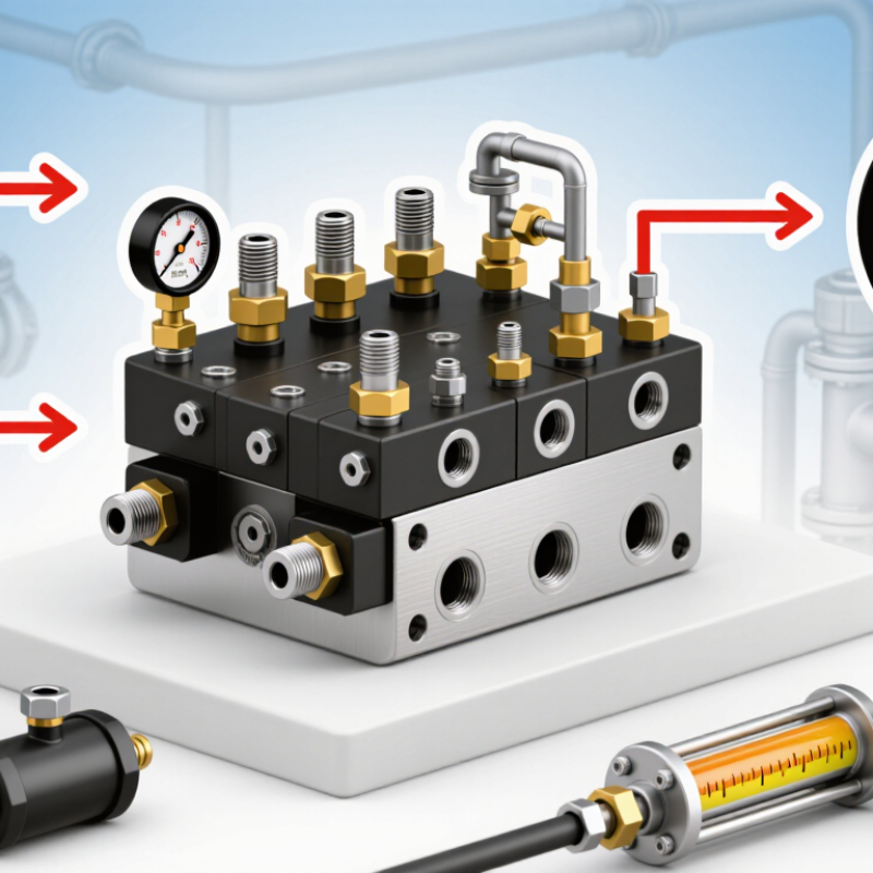
A relief valve block is more than a mounting piece for a relief valve. It connects the valve to the protected circuit and manages how pressure reaches it. Its main purpose is protection. When pressure rises above a set point, the valve can direct excess fluid away from sensitive components. The block may include isolation passages, test ports, a gauge connection, and service access. These features help technicians verify pressure, remove the valve, and limit unnecessary shutdowns. In practical systems, a well-arranged block also reduces tubing, leak points, and confusing maintenance work.
Choosing one requires checking pressure, flow, fluid compatibility, connection size, and temperature. A block rated for pressure alone may still fail operationally if flow capacity is too low. Check the valve’s set pressure against the system’s normal operating range. There should be enough margin to avoid constant opening during pressure spikes. Confirm that materials resist corrosion and that sealing materials suit the fluid and temperature. Small details matter. Port orientation should leave room for a wrench and pressure gauge. From field experience, cramped installations often create more trouble than the valve itself. That lesson is easy to underestimate.
Reliability depends on installation and maintenance. Mount the block securely, support connected tubing, and follow specified torque values. Before commissioning, inspect joints, test gauge readings, and verify the discharge route. Do not assume a factory setting matches actual operating conditions. Pressure readings can drift, and contamination may hold a valve slightly open. A documented inspection schedule helps reveal these issues early. Still, no selection guide replaces a site-specific review by a qualified engineer. I have found the overlooked question is often simple: what happens during maintenance? If isolation is needed, the block must support safe verification without defeating protection.
Choosing a relief valve block starts with three measurements: pressure, flow, and fluid. Record normal pressure, maximum operating pressure, and the required relief setting. Do not guess. A 10% pressure margin may be unsuitable when pressure spikes are severe.
Flow capacity must match the highest credible flow, not the average reading. Use pump displacement, actuator speed, and return-line restrictions to estimate demand. ISO 4413 requires hydraulic systems to manage excessive pressure and safely discharge stored energy. API 520 sizing practice also uses relieving pressure, temperature, fluid properties, and required capacity. These details matter. A valve block can have the correct thread and still restrict flow dangerously.
Fluid compatibility deserves equal attention. Check viscosity across the operating temperature range, then verify seal and body materials against the actual fluid. Water-based fluids, mineral oils, and biodegradable fluids behave differently. Contamination is another practical concern; ISO 4406 cleanliness codes can help define filtration needs. The U.S. Bureau of Labor Statistics recorded 5,486 fatal work injuries in 2022, although its report does not isolate relief-valve incidents. That limitation is worth noting. Safety data rarely explains one component’s failure. Field logs, pressure traces, and maintenance records provide better evidence. Select the block only after comparing those records with the manufacturer’s certified pressure-flow curves.
Choosing the right relief valve block depends on system pressure, flow, maintenance needs, and installation space. A compact manifold block suits systems with limited room and fewer connection points. An inline block works well where piping follows a straight path. Modular blocks offer flexibility when isolation, testing, or future expansion matters. The wrong type can restrict flow or make routine inspection awkward.
Material selection should match the fluid and environment. Stainless steel handles many corrosive conditions and outdoor installations, but it usually costs more. Carbon steel may suit dry, controlled environments with suitable protection. Brass can work for moderate pressures and compatible fluids. Do not select by pressure rating alone. Check temperature limits, corrosion data, and fluid compatibility together. A common field mistake is treating corrosion resistance as a purchasing detail. It is a design requirement.
Connection options also affect reliability. NPT threads are common, but installation requires careful sealing and correct torque. BSP threads may fit regional piping standards, yet they are not automatically interchangeable with NPT. SAE O-ring connections can reduce leakage when surfaces align correctly. Flanged connections are useful for larger lines and frequent servicing. Match the block port, tube, seal, and valve specification as one assembly. One awkward truth remains: a valve block may pass bench testing but fail after poor alignment. Leave tool clearance, support heavy tubing, and inspect every joint after pressurization.
How to Choose the Right Relief Valve Block for Your System?
A relief valve block should be selected around safety, not convenience. Check the pressure rating, temperature range, and applicable safety standards for your installation. Requirements may differ by country, industry, and fluid type. Request traceable test records and material certificates from the supplier. These documents support safer engineering decisions and easier inspections. A valve block for clean hydraulic oil may not suit corrosive chemicals or high-temperature service. Small differences matter.
Compatibility also includes port size, thread form, sealing materials, and installation direction. Confirm the block matches the relief valve, tubing, pressure gauge, and mounting space. In field work, I have seen leaks caused by incorrect thread assumptions. They looked compatible. They were not. Leave enough room for a wrench and future isolation procedures. Maintenance becomes difficult when every component is tightly packed.
Tips: Mark the set pressure near the block. Keep access clear. Plan periodic inspection, cleaning, and functional testing. Replace damaged seals promptly. Record test dates and pressure readings. Do not rely only on visual checks. A clean exterior can hide internal wear. Maintenance intervals should follow operating conditions, manufacturer guidance, and site experience. If the system cycles frequently, inspect it more often. I would also review the selection after the first service period, because real operating behavior may expose assumptions made during design.
Compare common hydraulic pressure levels when checking valve-block pressure ratings. Always confirm the maximum allowable working pressure, setting range, port size, fluid compatibility, applicable safety requirements, and maintenance access before selection.
Pressure conversions use 1 bar = 14.5038 psi. The values represent common reference points for hydraulic system design, not a substitute for the relief valve block manufacturer's certified ratings or the requirements of applicable standards such as ISO 4413.
Selecting the right relief valve block starts with the installation, not the catalogue. Confirm fluid type, temperature, pressure, flow rate, and available space. The block must match the valve’s connection size and pressure class. It should also allow safe isolation, testing, and replacement without disturbing nearby equipment. In field commissioning, small alignment errors often create large leakage risks. A clean calculation does not guarantee a reliable installation.
API 520 Part I and ISO 4126-1 provide recognized methods for sizing and selecting pressure-relief devices. For many ASME Section VIII applications, allowable accumulation is limited to 10% with one relieving device. Fire exposure cases can permit up to 21%, depending on the design basis. API 520 Part II also emphasizes discharge piping, reaction forces, and backpressure. These details affect operation. A valve block that looks compact may restrict flow or complicate inspection. The U.S. Chemical Safety Board’s investigation reports repeatedly connect weak relief-system management with serious process incidents. That evidence deserves attention, even when the equipment appears simple.
Tips: Keep the block accessible and clearly identified. Verify the set pressure against operating pressure. Check whether trapped fluid can expand between closed valves. Record torque, inspection dates, and test results. Do not rely on memory. During startup, watch for vibration, temperature changes, and unexpected pressure cycling. One practical improvement is often missed: involve maintenance personnel before final installation. Their concerns may reveal access problems that drawings hide.
| Selection Dimension | Typical Options or Range | Recommended Selection Guidance | Why It Matters During Operation |
|---|---|---|---|
| Primary System Function | Pressure protection, pressure isolation, test connection, or service access | Choose a block configuration that supports the required relief, isolation, venting, and testing functions. | A block that lacks a required function may prevent safe testing, maintenance, or depressurization. |
| System Medium | Hydraulic oil, water-glycol, water, compressed air, nitrogen, or other compatible fluids | Confirm compatibility of the valve body, seals, spring, seat, and any coating with the actual medium. | Chemical incompatibility can cause seal swelling, corrosion, leakage, or loss of pressure-control accuracy. |
| Operating Pressure | Common hydraulic applications: approximately 70–420 bar; specialized designs may differ | Select a block with a rated working pressure above the maximum continuous system pressure, including transient peaks. | Insufficient pressure rating can lead to deformation, leakage, or catastrophic component failure. |
| Relief Pressure Setting | Adjustable settings are commonly specified within the valve’s calibrated range | Set the relief pressure above normal operating pressure but below the lowest-rated component in the protected circuit. | The setting determines when excess pressure is discharged and protects pumps, actuators, tubing, and instruments. |
| Flow Capacity | Select according to required relief flow; small instrumentation blocks may handle low flow, while hydraulic blocks require higher capacity | Use the manufacturer’s flow-versus-pressure data and size the valve for the pump’s maximum possible discharge flow. | An undersized relief path may allow pressure to rise faster than the valve can safely control it. |
| Port and Connection Size | Metric or inch threaded ports; common sizes include 1/4, 3/8, 1/2, and 3/4 inch equivalents | Match the process connection standard, tubing size, sealing method, and available installation space. | Incorrect threads or sealing surfaces can cause leakage, difficult installation, and premature connection damage. |
| Valve Block Material | Carbon steel, stainless steel, or other application-specific alloys | Use stainless steel for corrosive, wet, outdoor, or hygienic environments when permitted by the design requirements. | Material selection affects corrosion resistance, pressure capability, service life, and total maintenance cost. |
| Seal and Soft-Part Material | Elastomer selection depends on fluid, temperature, and pressure conditions | Verify seal compatibility with the fluid, additives, cleaning agents, and expected temperature range. | The wrong seal material may harden, soften, crack, or lose sealing force. |
| Temperature Range | Typical industrial hydraulic designs: approximately −20°C to +100°C; confirm the exact rating | Consider ambient temperature, fluid temperature, startup conditions, and heat generated by the system. | Temperature changes can alter viscosity, cracking pressure, leakage rate, and seal performance. |
| Response and Stability | Direct-acting or pilot-assisted relief operation | Use a direct-acting design for simple, fast protection; consider pilot-assisted designs for higher flow and reduced pressure variation. | Response characteristics influence pressure spikes, system stability, noise, and component protection. |
| Mounting Arrangement | Inline, manifold-mounted, panel-mounted, or compact integrated block | Select the arrangement that provides adequate support, access to adjustment controls, and a clear discharge path. | Poor mounting can introduce vibration, mechanical stress, restricted access, or unsafe discharge routing. |
| Adjustment and Locking Method | Hex adjustment, hand adjustment, tamper-resistant cap, or locknut | Use a lockable or tamper-resistant adjustment where unauthorized changes could create a safety risk. | Uncontrolled adjustment may change the relief setting and compromise the protected equipment. |
| Discharge Routing | Return-to-tank, safe drain, vented discharge, or controlled downstream connection | Route discharged fluid to a safe location and ensure the downstream line does not create excessive back pressure. | Restricted discharge can reduce relief capacity and increase the pressure acting on the valve. |
| Testing and Maintenance | Pressure test port, isolation valve, drain port, replaceable cartridge, or serviceable adjustment assembly | Choose features that allow safe calibration checks, isolation, cleaning, and replacement without unnecessary system downtime. | Accessible service features support preventive maintenance and help verify continued pressure protection. |
| Documentation Requirements | Pressure rating, flow curve, materials, seal type, setting range, installation instructions, and test data | Do not approve the block until the datasheet and installation documentation match the actual system conditions. | Complete documentation supports correct installation, traceability, inspection, and future replacement. |