How to Choose the Right Diaphragm Valve?
Choosing the right diaphragm valve begins with understanding the process, not the product catalogue. Every application has different pressures, temperatures, fluids, and cleaning demands. A valve handling abrasive slurry needs different protection from one carrying sterile water. Small details matter.
In practical installations, engineers should examine the diaphragm material, body construction, pressure rating, flow direction, and connection style. PTFE may suit aggressive chemicals, while elastomers can perform better in other services. Compatibility must be checked against the actual fluid, concentration, temperature, and operating cycle. Guesswork is expensive.
The correct diaphragm valve should also support reliable maintenance. Consider whether the diaphragm can be replaced without removing the entire valve. Inspect the available space around the actuator and the accessibility of bolts, seals, and drains. Operators often notice these issues only after installation. That is a useful warning.
Actuation choices deserve equal attention. Manual, pneumatic, and automated options each affect response time, control accuracy, and maintenance requirements. A fail-safe position may be essential for a critical process. However, not every system needs complex automation. Simpler equipment can be more dependable when conditions are stable.
This guide compares the main selection factors in a clear, application-focused way. It considers performance, lifecycle cost, hygiene, and safety. Manufacturer data should always be verified against current site conditions and recognized technical standards. No single diaphragm valve fits every process. The best choice is the one that performs consistently, can be inspected easily, and remains suitable when operating conditions change.
Diaphragm Valve Types: Weir, Straight-Through, and 2- or 3-Way Designs
Choosing the right diaphragm valve starts with the process, not the catalog photo.
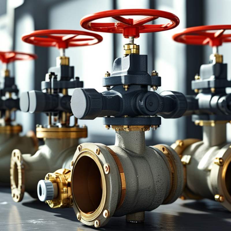
In field inspections, I look at fluid abrasiveness, solids, temperature, pressure, and cleaning requirements. A weir diaphragm valve suits many corrosive or slurry services because its raised weir supports controlled shutoff. It also reduces diaphragm travel. However, the weir can restrict flow and collect residue in some applications.
A straight-through diaphragm valve offers a smoother passage for viscous fluids, powders, and liquids containing larger particles.
It usually creates less obstruction than a weir design. This can help reduce clogging and pressure loss. The trade-off is important. The diaphragm may face greater movement and wear, especially during frequent cycling. I once selected a straight-through model for easy drainage, but underestimated actuator speed. The result was unnecessary mechanical stress.
Two-way designs handle simple isolation or flow control between inlet and outlet.
They are often easier to maintain and troubleshoot. Three-way diaphragm valves direct flow between multiple lines, making them useful for mixing, diversion, or hygienic routing. Port arrangement matters more than it first appears. A wrong configuration can send fluid toward the wrong vessel. Check the flow path carefully. During selection, confirm connection size, actuation method, diaphragm material, pressure rating, and cleaning procedure. Installation space also deserves attention. A compact valve may be convenient, yet difficult to inspect or replace when surrounded by piping.
Size by Flow Coefficient Cv, Pressure Drop, and ANSI Class Ratings
Choosing the right diaphragm valve starts with flow, not pipe diameter. Size it by the required flow coefficient, Cv, and the pressure drop available across the valve. For liquid service, the common sizing relationship is Cv = Q × √(SG/ΔP), where Q is flow in gallons per minute, SG is specific gravity, and ΔP is pressure loss in psi. Crane Technical Paper 410 and IEC 60534-2-1 provide established methods for control-valve flow calculations. A valve with excessive Cv may operate nearly closed, causing unstable control. A valve with insufficient Cv may remain fully open and still miss the target flow. I have seen both mistakes during practical selection reviews.
Pressure drop must also be checked against the system curve, pump capability, and cavitation risk. Do not assume a 2-inch valve is suitable for a 2-inch line. A smaller valve can create unnecessary velocity and erosion; a larger valve can reduce control sensitivity. ANSI Class ratings, defined through ASME B16.34 pressure-temperature requirements, should be matched to the actual fluid temperature and pressure. Class 150 is not a universal 150 psi limit. Its allowable pressure changes with material and temperature. The 2024 ASME B16.34 requirements reinforce this point, although engineers sometimes overlook the temperature correction. Confirm the diaphragm material, actuator force, shutoff demand, and cycle frequency before final selection. That last check is easy to skip.
How to Choose the Right Diaphragm Valve? - Size by Flow Coefficient Cv, Pressure Drop, and ANSI Class Ratings
Design basis: The pressure-drop examples below use clean water at approximately 20°C with a specific gravity of 1.00. Cv values shown for valve sizes are representative planning values only; the certified Cv for a particular diaphragm, weir, body material, and flow path must be confirmed from the valve manufacturer.
| Selection Parameter |
What It Means |
Practical Design Guidance |
| Flow coefficient, Cv |
The U.S. flow coefficient is the water flow in U.S. gallons per minute that produces a 1 psi pressure drop across the valve. |
Calculate the required Cv at the design flow, then select a valve with sufficient capacity while avoiding an excessively oversized valve. |
| Pressure drop, ΔP |
The difference between inlet and outlet pressure while the valve is flowing. |
Lower ΔP generally reduces pumping energy. A control valve may require a deliberate pressure drop for stable throttling. |
| ANSI/ASME pressure class |
A standardized pressure-temperature designation such as Class 150 or Class 300; it is not a universal constant pressure rating. |
Select a class whose material-specific pressure-temperature rating exceeds the maximum operating pressure and temperature. |
| Valve size |
The nominal pipe size and effective flow passage through the diaphragm valve. |
Do not select by pipe diameter alone. Compare the required Cv, velocity, shutoff conditions, and available pressure drop. |
| Flow medium |
The liquid, gas, slurry, or corrosive service passing through the valve. |
Check diaphragm and body compatibility, solids content, viscosity, temperature, corrosion, and cleaning requirements. |
Basic Cv Sizing Equations
| Service |
Equation |
Variables |
| Liquids |
Cv = Q × √(SG ÷ ΔP) |
Q = flow in U.S. gal/min; SG = specific gravity; ΔP = pressure drop in psi. |
| Pressure drop from a known Cv |
ΔP = SG × (Q ÷ Cv)² |
Use consistent U.S. customary units and verify that the result is within the valve's allowable operating range. |
| Metric flow conversion |
1 U.S. gpm ≈ 0.227 m³/h |
Convert the design flow before applying the equation if the flow data is supplied in metric units. |
Representative Diaphragm Valve Capacity Guide
| Nominal Size |
Representative Cv Range |
Approximate Water Flow at ΔP = 5 psi |
Typical Application Consideration |
| 1/2 in (DN15) |
3–10 |
6–22 gpm |
Low-flow utility, laboratory, dosing, and hygienic service. |
| 1 in (DN25) |
12–35 |
27–78 gpm |
General process isolation and moderate-flow throttling. |
| 2 in (DN50) |
45–125 |
101–280 gpm |
Process lines, slurry service, and larger isolation duties. |
| 3 in (DN80) |
100–260 |
224–582 gpm |
High-flow process and utility applications where diaphragm protection is required. |
| 4 in (DN100) |
180–450 |
403–1,007 gpm |
Large process pipelines; confirm actuator thrust and diaphragm operating limits. |
Worked Water-Flow Examples
| Design Flow |
Selected Cv |
Specific Gravity |
Calculated ΔP |
Interpretation |
| 20 gpm |
25 |
1.00 |
0.64 psi |
Low pressure loss; check that the valve can still provide stable control at low travel. |
| 40 gpm |
20 |
1.00 |
4.00 psi |
A moderate pressure drop suitable for many general water services. |
| 100 gpm |
45 |
1.00 |
4.94 psi |
Compare this pressure drop with the available pump head and the required system flow. |
| 250 gpm |
100 |
1.00 |
6.25 psi |
A larger valve may be required if the system cannot tolerate this pressure loss. |
| 100 gpm |
45 |
1.20 |
5.93 psi |
Higher-density liquid produces a higher pressure drop at the same flow and Cv. |
ANSI/ASME Pressure Class Selection
| Pressure Class |
General Use Profile |
Important Selection Requirement |
| Class 150 |
Common low-to-moderate pressure process and utility service. |
Verify the pressure-temperature rating for the specific body and lining material; do not treat 150 as a fixed 150 psi rating at all temperatures. |
| Class 300 |
Higher-pressure service or applications requiring additional design margin. |
Confirm flange dimensions, bolt pattern, diaphragm pressure rating, and the complete pressure-temperature table. |
| Class 600 and above |
Specialized high-pressure service where the valve design is specifically rated for the duty. |
Confirm that the diaphragm valve design, actuator, body, lining, end connection, and applicable code all support the required pressure and temperature. |
Final Selection Checklist
| Check |
Acceptance Criteria |
| Required Cv |
The selected valve Cv meets or exceeds the calculated process requirement at the design flow. |
| Pressure drop |
The calculated ΔP fits within the available pump head or system pressure budget. |
| Pressure class |
The material-specific pressure-temperature rating is above the maximum design pressure and temperature, including applicable surge conditions. |
| Material compatibility |
The diaphragm, body, lining, and wetted components are compatible with the process fluid, concentration, temperature, and cleaning chemicals. |
| Operating mode |
The valve is suitable for isolation, throttling, slurry handling, vacuum service, or automated cycling as required. |
| Installation standard |
End connections, face-to-face dimensions, flange drilling, actuator requirements, and maintenance clearances match the piping system. |
Choose Diaphragm Materials by Chemical Compatibility and Cycle-Life Data
How to Choose the Right Diaphragm Valve?
Choosing the right diaphragm valve starts with material selection, not body size alone. In field inspections, I have seen compatible-looking materials fail after repeated cleaning cycles. Chemical compatibility requires more than checking a chemical name. Review concentration, temperature, pressure, exposure time, and cleaning agents. A diaphragm that survives cool water may soften in hot, concentrated service. Small details matter.
Request documented compatibility charts and cycle-life data from qualified technical sources. Check the test temperature, pressure differential, stroke frequency, and failure criteria. A diaphragm rated for one million cycles in clean water may perform differently with abrasive particles or rapid pressure changes. Ask whether testing included thermal cycling and repeated sanitation. Data without test conditions is weak evidence.
A short application trial can reveal practical risks. Run the valve under actual pressure and temperature conditions. Record leakage, cracking, stiffness, and response time after defined cycles. Visual inspection alone can miss early fatigue. I once relied too heavily on a material chart and underestimated cleaning stress. That mistake changed my selection process. Compare laboratory data with operating evidence, then allow a safety margin for real equipment variation.
How to Choose the Right Diaphragm Valve?
Compare diaphragm materials by chemical compatibility and typical cycle-life performance. Compatibility ratings are screening-level guidance; actual service life depends on temperature, pressure, stroke frequency, media concentration, and valve design.
Chemical compatibility score: 1 = limited compatibility, 5 = broad compatibility. Cycle-life values are representative engineering benchmarks shown in thousands of actuation cycles and should be confirmed with application-specific test data.