Print Logo

What Is a Cross Slide Table and How Does It Work?

What Is a Cross Slide Table and How Does It Work?

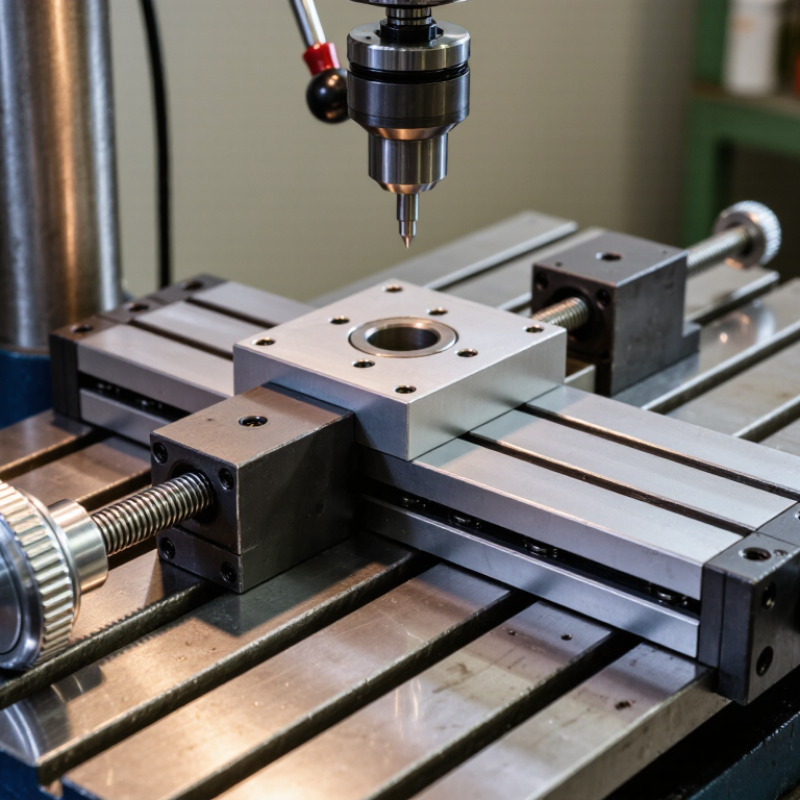
A Cross Slide Table is a compact mechanical platform that moves a workpiece or tool in two directions. Its axes usually run perpendicular to each other. This arrangement supports controlled positioning during drilling, milling, grinding, and small machining operations.

The table often uses dovetail slides, lead screws, handwheels, and adjustable gib strips. Turning one handwheel moves the upper slide. The second handwheel shifts the lower slide across the first axis. Picture a drill press setup: the workpiece rests on the table, while each small handle movement brings the hole closer to its intended position.

Small movements matter.

Robert H. Todd, a manufacturing engineering educator and author, has emphasized that “accuracy depends on the entire process, not one machine component.” That principle applies directly here. A rigid Cross Slide Table cannot compensate for a bent tool, loose mounting, poor measurement, or careless feeding.

In practical use, operators check backlash before cutting. They also clean chips from the ways and apply suitable lubrication. These details seem minor. They are not.

The mechanism is simple, but precision is conditional. A budget table may show noticeable play after repeated use. A hardened, well-adjusted model can provide smoother travel and better repeatability. Still, “precision” should not be accepted blindly. The real result depends on setup, material, tooling, operator technique, and maintenance. This article explains the table’s construction, movement, adjustment, and practical limitations.

What Is a Cross Slide Table and How Does It Work?

What Is a Cross Slide Table and What Is Its Purpose?

What Is a Cross Slide Table and What Is Its Purpose?

A cross slide table is a precision platform that moves a workpiece in two directions. One axis moves forward and backward. The other moves left and right. Handwheels, lead screws, or powered drives control these movements. This design helps operators position material beneath a drill, cutter, grinder, or measuring tool. Its main purpose is controlled adjustment, not simply holding the workpiece. A rigid table can improve alignment, repeatability, and operator control during small machining tasks.

The International Federation of Robotics reported 541,302 industrial robot installations worldwide in 2023. That figure shows the industry’s growing need for repeatable positioning. A cross slide table supports this need at a smaller, more practical scale. It can set drilling patterns, guide edge finishing, and make incremental corrections without repositioning the entire machine. However, it does not remove every error. Backlash, loose fasteners, poor lubrication, and uneven clamping still affect accuracy. A 0.1-millimeter adjustment may look minor, but it matters when holes must align closely.

Tips: Clean the slides before use. Check backlash regularly. Tighten the workpiece firmly, but avoid distortion. Set the table near the center of its travel when possible. That position usually provides better stability. Read the machine’s accuracy data, not just its scale markings. Experimental checks remain valuable, because real workshop conditions can differ from specifications.

What Is a Cross Slide Table and How Does It Work?

A cross slide table provides controlled movement along two perpendicular axes. Its handwheel usually drives a lead screw, converting rotary motion into precise linear travel.

Chart explanation: The values show the theoretical linear travel produced by one complete handwheel revolution for common lead screw pitches. Metric values equal the pitch in millimeters, while inch values are converted using 25.4 ÷ TPI. Actual cross slide tables may use different screw pitches and may include backlash or adjustment errors.

Key Components and Structural Design of a Cross Slide Table

What Is a Cross Slide Table and How Does It Work?

A cross slide table is a compact positioning unit that moves a workpiece sideways across a machine bed. Its main structure includes a rigid base, sliding carriage, lead screw, handwheel, and locking mechanism. The base anchors the table and spreads cutting forces into the machine frame. The carriage travels along guideways, commonly dovetail slides or precision linear rails. Turning the handwheel rotates the lead screw, converting manual rotation into controlled linear movement. A calibrated dial helps the operator estimate travel distance, although scale readings can vary slightly with wear and setup errors.

Structural design determines accuracy, stiffness, and service life. A dovetail slide often uses an adjustable gib to remove unwanted play. Too much tightening creates heavy movement and uneven wear. Too little tightening allows vibration during cutting. The lead screw may use a plain nut or a lower-friction nut system, depending on the required precision. Clamps secure the carriage after adjustment. I have found that a strong table can still perform poorly when its mounting surface is uneven. That detail is easy to underestimate.

Tips: Keep guideways clean and lightly lubricated. Check backlash before precision work. Move the carriage through its full travel and feel for tight spots. Do not rely only on the handwheel scale. A test indicator can reveal alignment errors that the operator cannot see. Recheck the setup after tightening, because clamping can shift a small workpiece. Calibration is never permanent.

How a Cross Slide Table Moves Along Two Axes

A cross slide table is a compact positioning device used on drills, mills, and workshop fixtures. Its upper platform travels across a lower platform, allowing movement along two separate axes. One axis moves left and right. The other moves forward and backward. Together, these movements create a controlled XY path for drilling, slotting, or light milling. The design looks simple, but accurate adjustment requires patience.

Each axis usually operates through a handwheel connected to a threaded leadscrew. Turning the X-axis handwheel rotates its screw, pushing the table sideways through a fitted nut. The Y-axis handwheel controls the second platform in the same way. Dovetail guides or linear rails keep both sections aligned while they move. Graduated dials show approximate travel, while a ruler or measuring tool confirms the actual position. Small errors still matter.

In practical use, I lock the unused axis before cutting. This reduces vibration and prevents accidental movement. Backlash can appear when the screw changes direction, so I approach the final setting from one direction whenever possible. A heavy cut may flex the table or shift the workpiece. I have sometimes trusted the dial too much. That was a mistake. No setup is perfect. Check the workpiece after positioning, especially when the cut must meet another hole or edge.

Common Types and Drive Mechanisms

A cross slide table is a compact positioning unit with two perpendicular axes. It lets a workpiece, tool, or sensor move left-right and forward-backward. Each axis runs on guideways, while a drive mechanism converts rotary input into controlled linear travel. In practice, the table feels simple, but alignment errors can quickly affect drilling, milling, inspection, or assembly accuracy.

Common types include manual, motorized, and compound cross slide tables. Manual models usually use handwheels and lead screws. They suit repair benches, teaching rigs, and low-volume machining. Motorized versions use stepper or servo motors for repeatable movement. Compound tables add stacked axes, offering broader adjustment but also increasing height, weight, and possible flex. A useful warning: more travel does not always mean better performance.

Lead screws provide strong positioning force and economical construction. Ball screws reduce friction and backlash, making them suitable for frequent CNC movement. Rack-and-pinion drives support longer travel, although they may require careful adjustment. Linear motors deliver rapid acceleration, but their price and tuning demands can limit practical use.

The International Federation of Robotics reported 4.28 million industrial robots operating worldwide in 2023. That scale increases demand for repeatable positioning components. A 2024 market analysis by Grand View Research also identifies automation as a major driver of CNC equipment growth. These figures support the trend, but they do not guarantee table accuracy. Load, lubrication, thermal growth, and operator setup still matter. Small errors become visible.

Typical Applications and Selection Considerations

What Is a Cross Slide Table and How Does It Work?

A cross slide table supports controlled movement along two perpendicular axes. Its upper platform moves sideways, while the lower section travels forward or backward. A handwheel, leadscrew, or motor controls each direction. Turning the screw advances the platform through a measured distance. This arrangement helps position workpieces accurately without moving the entire machine.

Typical applications include drilling, milling, grinding, inspection, and small fixture adjustments. Workshops often use cross slide tables for repeatable positioning on compact equipment. However, the best model depends on the task. Check the required travel range, working load, platform size, and adjustment resolution. A longer travel range may reduce rigidity. A fine leadscrew may improve control but slow daily operation. Dovetail slides often provide strong support, while linear bearings can offer smoother movement. Dust, coolant, and vibration also affect service life. These details are easy to underestimate.

Tips: Measure the actual workpiece and fixture together. Leave clearance around the handwheels. Check backlash before precision work. Do not select capacity by weight alone; consider the load’s height and position. A heavy part mounted far from the center can create excessive twisting force. Recheck alignment after installation. Perfect accuracy is rarely achieved immediately, and my first assumption may be wrong. Practical testing under real load usually reveals more than a catalogue specification.

What Is a Cross Slide Table and How Does It Work? - Typical Applications and Selection Considerations
Category Key Dimension Description Typical Applications Selection Considerations
Basic Definition Mechanical Structure A cross slide table is a compact positioning platform made of two sliding stages arranged at right angles. One stage provides movement along the X-axis, while the other provides movement along the Y-axis. Manual positioning, inspection fixtures, laboratory setups, and small machine tools. Confirm the required travel direction, available installation space, and compatibility with the mounting surface.
Operating Principle Two-Axis Motion Turning a handwheel or driving a screw moves one stage linearly. The second stage is mounted on top of the first and provides motion perpendicular to it, allowing controlled movement in two horizontal directions. Component alignment, tool positioning, sample adjustment, and drilling or milling setup. Select independent X and Y adjustment when precise two-axis alignment is needed.
Drive Mechanism Lead Screw or Ball Screw Lead screws are common in manual and general-purpose tables. Ball screws reduce friction and backlash and are more suitable for motorized systems requiring improved positioning performance. Lead screws: manual machining and adjustment. Ball screws: CNC equipment, automation, and repeated positioning. Consider required accuracy, repeatability, operating speed, load, maintenance, and budget.
Motion Control Manual or Motorized Manual tables use handwheels, knobs, or micrometer heads. Motorized versions use stepper motors, servo motors, or other actuators for programmable movement. Manual inspection and setup; automated assembly, measurement, scanning, and machine-tool positioning. Choose manual control for occasional adjustment and motorized control for automation, remote operation, or repeatable cycles.
Travel Range X/Y Travel Travel range is the maximum linear distance available on each axis. Compact tables may provide short travel for fine adjustment, while larger tables support broader positioning. Short travel: optical alignment and inspection. Longer travel: machining, fixture positioning, and production equipment. Specify the required travel on both axes and allow additional clearance for workholding and tool access.
Load Capacity Static and Dynamic Load Load capacity depends on bearing design, stage size, screw arrangement, load direction, and the distance between the load center and the table surface. Supporting workpieces, inspection fixtures, cutting tools, sensors, cameras, and laboratory equipment. Include the workpiece, fixture, tooling, and any dynamic forces. Use a safety margin rather than selecting at the exact rated limit.
Guidance System Dovetail, Linear Bearing, or Profile Rail Dovetail slides provide robust guided motion and are often adjustable. Rolling-element bearings and profile rails generally offer lower friction and smoother motion. Dovetail slides: machining and rugged manual adjustment. Linear bearings or rails: precision positioning and automated motion. Match the guide type to the required rigidity, smoothness, environmental conditions, speed, and maintenance schedule.
Accuracy Positioning Accuracy and Repeatability Accuracy describes how closely the table reaches a commanded position. Repeatability describes how consistently it returns to the same position. These values are affected by screw quality, guide clearance, stiffness, and assembly. Dimensional inspection, optical alignment, precision assembly, and controlled tool positioning. Define whether the process requires high absolute accuracy, high repeatability, or simply convenient manual adjustment.
Backlash Clearance in the Drive System Backlash is unwanted lost motion caused by clearance between mating screw and nut components. It can affect bidirectional positioning and contouring accuracy. Critical in CNC machining, precision measurement, and automated positioning that changes direction frequently. Consider an anti-backlash nut, preloaded screw, or ball screw when reversing direction must not create significant positioning error.
Rigidity Resistance to Deflection Rigidity is the table's ability to resist bending, twisting, and vibration under load. A rigid platform helps maintain alignment and cutting stability. Milling, drilling, grinding, heavy fixtures, and applications involving cutting forces. Evaluate table thickness, guide spacing, support area, material, and the distance from the load center to the slide.
Table Surface Mounting Pattern and Work Area The upper platform may include threaded holes, clearance holes, slots, or a plain surface for attaching fixtures and components. Mounting vises, clamps, sensors, optical components, probes, and custom fixtures. Verify hole spacing, thread type, usable surface area, and access for tools and fasteners.
Materials Steel, Aluminum, or Cast Iron Steel and cast iron generally provide higher stiffness and wear resistance. Aluminum reduces weight and is useful where portability or lower moving mass is important. Steel or cast iron: machining and heavy-duty fixtures. Aluminum: laboratory, optical, and lightweight automation systems. Balance mass, stiffness, corrosion resistance, thermal behavior, and expected wear.
Environment Dust, Chips, Moisture, and Temperature Contaminants can increase friction and wear, while moisture may cause corrosion. Temperature changes can affect dimensions and positioning accuracy. Clean laboratories, machine shops, production lines, outdoor equipment, and process environments. Consider covers, seals, corrosion-resistant materials, lubrication requirements, cleaning access, and operating temperature.
Common Applications Machining and Fabrication Cross slide tables are used to position workpieces or tools during drilling, milling, engraving, grinding, and other operations requiring controlled planar movement. Drill presses, small mills, engraving machines, fixture systems, and custom fabrication equipment. Prioritize rigidity, load capacity, travel, backlash control, and compatibility with cutting forces.
Common Applications Inspection and Measurement The table provides fine adjustment for positioning a part, probe, camera, sensor, or measuring device relative to a reference point. Dimensional inspection, visual inspection, sensor alignment, and laboratory measurement. Prioritize smooth motion, low backlash, repeatability, fine adjustment resolution, and stable mounting.
Common Applications Optical and Laboratory Equipment Compact cross slide tables allow precise horizontal adjustment of samples, lenses, detectors, stages, and experimental fixtures. Optical alignment, microscopy accessories, research equipment, and test benches. Check vibration resistance, adjustment sensitivity, surface flatness, cleanliness, and compatibility with the laboratory setup.
Common Applications Automation and Assembly Motorized cross slide tables can move components through programmed X/Y positions for assembly, dispensing, testing, marking, or inspection. Pick-and-place systems, dispensing equipment, camera inspection, testing stations, and light-duty automation. Evaluate cycle rate, acceleration, motor compatibility, controller interface, cable routing, and repeatability.
Maintenance Lubrication and Adjustment Proper lubrication reduces wear and friction. Periodic inspection may be needed to check fasteners, guide clearance, screw condition, and surface contamination. All manual and motorized cross slide table installations. Select a design with accessible lubrication points and adjustment features appropriate for the operating environment.