How to Choose a Spring Tensioner in 2026?
Choosing a Spring Tensioner in 2026 requires more than comparing price, load ratings, or catalogue photographs. The correct choice must match the machine’s speed, vibration, temperature, duty cycle, and maintenance access. A tensioner may look suitable on a workbench, yet fail beside a hot conveyor pulley or a rapidly cycling drive.
Industry data shows why reliability deserves attention. The International Federation of Robotics reported 541,302 industrial robots installed worldwide in 2023, with more than 4.28 million robots operating globally. These systems depend on stable motion, controlled belt tension, and repeatable component performance. The International Energy Agency’s Global EV Outlook 2025 also reported more than 17 million electric cars sold in 2024. This expanding production environment places greater pressure on compact, durable, and serviceable mechanical components. A Spring Tensioner can support consistent force, but only when its material, stroke, preload, and mounting design suit the application.
The selection process should begin with real operating evidence. Measure belt movement, inspect wear patterns, and record the actual temperature near the spring. Do not rely on ideal laboratory values alone. Manufacturer load curves, fatigue data, corrosion testing, and traceable quality procedures provide stronger evidence than marketing claims. ISO 9001 certification can indicate controlled manufacturing, although it does not guarantee a perfect product.
There is no universal tensioner. That point is easy to overlook. Market reports often group many components together, so their statistics cannot prove one model will perform better. A careful 2026 decision combines engineering calculations, supplier experience, field feedback, and a realistic maintenance plan. Reliability is designed, not assumed.
Define Tensioner Type, Load Range, and Stroke with ISO 10243 Ratings
How to Choose a Spring Tensioner in 2026?
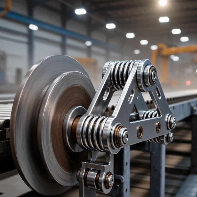
Start by defining the tensioner type. A compression-spring tensioner suits guided assemblies that push against a moving part. An extension design works when the spring must pull two points together. For rotating belts or chains, confirm the tensioner can manage side loads and repeated motion. The wrong type may fit the drawing but fail during real operation.
Check the working load, not only the spring’s maximum force. ISO 10243 ratings are useful when the tensioner uses standardized die springs. These ratings help compare spring loads, dimensions, and expected performance. Select a spring whose rated load covers the normal operating range without reaching coil bind. Leave practical safety margin. Too much margin can reduce sensitivity.
Stroke matters just as much. Measure the full movement from relaxed position to the maximum compressed or extended position. Then compare that distance with the spring’s recommended working stroke. A short stroke can cause unstable tension. An excessive stroke can accelerate fatigue. In 2026, I would also request load-deflection data and cycle-life information, not just a catalog rating. ISO 10243 does not automatically certify every complete tensioner assembly. That distinction is easy to miss. It deserves attention. A useful field check is simple: mark the installed position, cycle the mechanism slowly, and inspect alignment, noise, and heat. If the load seems correct but wear appears early, the problem may be friction or poor guidance rather than spring strength.
Calculate Preload and Working Deflection from Force–Deflection Curves
How to Choose a Spring Tensioner in 2026?
Calculate Preload and Working Deflection from Force–Deflection Curves
A spring tensioner should be selected from measured force data, not catalog length alone. Start by identifying the installed position and its force on the force–deflection curve. That force is the preload. For example, if installation occurs at 12 mm extension and the curve shows 34 N, the preload is 34 N. Record the actual position with a caliper.
Working deflection is the movement between the minimum and maximum operating positions. If the tensioner moves from 12 mm to 24 mm, its working deflection is 12 mm.
Calculate the spring rate using two curve points:
k = (F2 − F1) ÷ (x2 − x1)
With forces of 34 N and 70 N, the rate is 3 N/mm. The expected operating force can then be checked at every important position.
The curve is rarely perfect. Friction, coil contact, temperature, and manufacturing variation can change the reading. Test several samples at a controlled speed, preferably after repeated cycling. A practical design may require 40 N at the lowest position and 65 N at the highest. Do not treat those values as exact forever. My first estimate often looks convincing, yet the return path may show hysteresis. Allow room for fatigue and assembly tolerance, then verify the tensioner on the real mechanism. A loose pivot can distort the curve.
Select ASTM A228 Wire or Stainless Steel for 10⁶-Cycle Fatigue Life
Choosing a spring tensioner in 2026 starts with its fatigue target. For 10⁶ cycles, wire selection matters, but stress design matters more. ASTM A228/A228M defines requirements for high-carbon music wire. It does not guarantee a specific fatigue life. The Spring Manufacturers Institute’s Spring Design and Application Manual also links durability to stress range, mean stress, surface quality, and operating temperature.
ASTM A228 wire offers high tensile strength and efficient energy storage. It suits clean, dry assemblies with stable temperatures. However, moisture, salt, or condensation can quickly damage its surface. Stainless steel, such as corrosion-resistant spring wire, provides stronger environmental protection. Its fatigue strength may be lower after forming, depending on grade and diameter. That trade-off is often missed. Corrosion resistance does not automatically mean longer fatigue life.
Use the manufacturer’s S-N data, not a generic strength table. ASM Handbook, Volume 19, reports that surface condition and corrosion can shift fatigue performance significantly. For a 10⁶-cycle target, engineers should calculate corrected alternating stress, inspect formed hooks, and test beyond one million cycles. A practical validation plan may use 1.2 million cycles under real load, temperature, and exposure. ASTM testing guidance supports controlled fatigue evaluation, but field conditions remain less predictable. My own design preference is conservative: select stainless steel for outdoor tensioners, then confirm its lower stress capacity experimentally. The extra test costs less than an unnoticed relaxation failure.
How to Choose a Spring Tensioner in 2026?
ASTM A228 music wire or stainless spring wire for a 10⁶-cycle fatigue target
Engineering interpretation: ASTM A228 music wire generally provides the higher tensile-strength range and is often preferred when maximum elastic force and compact size are the priorities. Stainless spring wire, typically based on 302/304 stainless grades, offers better corrosion resistance but usually has a lower tensile-strength range. The ranges shown are representative engineering values and vary with wire diameter, cold work, heat treatment, and temper. A 10⁶-cycle life cannot be guaranteed from material selection alone; mean stress, alternating stress, surface condition, bend radius, and corrosion exposure must be verified by fatigue analysis or testing.
Data basis: representative ranges commonly specified for ASTM A228 carbon spring wire and ASTM A313 stainless spring wire; actual certified values depend on diameter and material condition.
Validate Bearing Life, Safety Factors, and Service Intervals Using ISO 281
How to Choose a Spring Tensioner in 2026?
A spring tensioner needs more than a correct spring rate. Its bearing must survive fluctuating radial loads, shock, misalignment, and heat. ISO 281:2007 defines basic rating life, L10, as the operating life reached by 90% of identical bearings under controlled conditions. For ball bearings, the life exponent is 3. For roller bearings, it is 10/3. Use the actual tensioner load spectrum, not only the average load.
Check equivalent dynamic load at minimum and maximum belt tension. Then calculate L10 in revolutions and convert it into operating hours. ISO 76:2006 also supports static load evaluation through a safety factor. A practical design should review peak starting loads, belt vibration, and spring surge. A spreadsheet can still lie. Real assemblies often suffer from contamination or alignment errors that the formula cannot see.
Service intervals should reflect both calculation and field evidence. The U.S. Department of Energy’s Operations & Maintenance Best Practices guide reports predictive maintenance savings of 8–12% against preventive maintenance and 30–40% against reactive maintenance. That supports condition-based inspection, but not blind optimism. Set an initial inspection after commissioning, then examine noise, temperature, grease leakage, and belt tracking. Revise the interval when measured data disagrees with ISO 281 predictions. A conservative safety factor is useful, yet an unexplained factor can hide poor load assumptions.
How to Choose a Spring Tensioner in 2026? - Validate Bearing Life, Safety Factors, and Service Intervals Using ISO 281
| Application Case | Bearing Type | Dynamic Rating C
(kN) | Equivalent Load P
(kN) | Speed
(r/min) | ISO 281 L10
(million rev) | L10 Life
(hours) | Required Tension
(N) | Peak Spring Force
(N) | Force Safety
Factor | Planned Service
Interval (hours) | Selection Assessment |
| Light-duty auxiliary belt | Single-row deep-groove ball bearing | 12.0 | 0.65 | 1,800 | 6,290 | 58,240 | 420 | 630 | 1.50 | 2,000 | Suitable; bearing life is well above the planned inspection interval. |
| Industrial conveyor drive | Single-row deep-groove ball bearing | 8.8 | 0.90 | 2,400 | 935 | 6,490 | 700 | 1,120 | 1.60 | 1,620 | Suitable; inspect more frequently if dust or belt misalignment is present. |
| High-load packaging machine | Cylindrical roller bearing | 18.0 | 2.40 | 1,200 | 1,040 | 14,440 | 1,600 | 2,400 | 1.50 | 2,000 | Suitable when radial load, shock loading, and shaft alignment are controlled. |
| Compact high-speed belt system | Single-row deep-groove ball bearing | 6.3 | 1.60 | 3,000 | 61 | 339 | 900 | 1,260 | 1.40 | 85 | Marginal; use a larger bearing, reduce load, or shorten the service interval. |
Calculation basis: For ball bearings, ISO 281 basic rating life is calculated as L10 = (C/P)3 million revolutions. For roller bearings, the exponent is 10/3. Operating life in hours is calculated as L10h = L10 × 106 / (60 × speed). The force safety factor is peak spring force divided by required operating tension. The planned service interval is set at 25% of the calculated L10 life, limited to 2,000 hours, and must be confirmed against temperature, contamination, lubrication, shock load, and belt condition.
Engineering note: ISO 281 L10 represents the basic rating life associated with 90% reliability under defined load and lubrication conditions. It does not replace verification of spring fatigue strength, maximum allowable deflection, mounting stiffness, shaft alignment, pulley balance, temperature limits, or the effects of contamination and transient loads.