Best High Density Fiber Optic Cable Types for 2026?
High-density fiber is not one cable design. It is a family of choices shaped by fiber count, pathway space, connector strategy, and future capacity needs. In 2026, ribbon cables, micro-distribution cables, and compact trunk assemblies are common options for data centers and enterprise networks. Each solves a different problem. More fibers in less space can ease congestion, but it can also make access and repair less forgiving.
Jim Hayes, founder of the Fiber Optic Association and a longtime fiber-optics educator, is known for practical guidance on fiber selection. A useful paraphrase of that approach is: “Choose the cable for the route and service needs, not fiber count alone.” That distinction matters. A ribbon design may speed mass fusion splicing, while a micro-distribution cable can fit tight pathways. MPO-based trunks can simplify dense links, but polarity and connector planning need careful attention.
Small details matter.
This guide compares the leading High Density Fiber Optic Cable types for 2026, including where each design fits and what trade-offs deserve a closer look. Expect practical factors: duct fill, bend radius, splice method, connector access, and the technician’s room to work. A crowded rack can look efficient on paper. In the field, labels may be hard to read, and a cable route may block access to neighboring ports. Those realities are easy to underestimate. The best choice is therefore not always the cable with the highest fiber count. It is the one that meets capacity goals while remaining installable, testable, and maintainable.
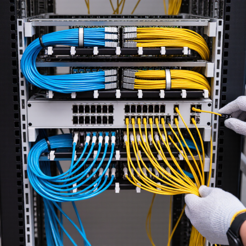
Define High Density: Compare 12-, 24-, and 288-Fiber Cable Counts
High density has no universal fiber-count threshold. It describes how much capacity fits within a cable’s diameter and the pathway available. That distinction matters. A 12-fiber cable often serves a small link or a few devices, with straightforward routing and termination. A 24-fiber cable doubles that capacity without necessarily doubling the cable’s outside diameter. The actual size depends on construction, such as fiber type, strength members, and jacket design.
A 288-fiber cable places many fibers in one route, often for backbone links or crowded pathways. High capacity, less forgiving. Installation may require larger bend-radius allowances, careful pulling, and enough tray space at splice or termination points. A high fiber count can reduce the number of separate cables, but it can also make handling and troubleshooting more demanding. Count alone does not define density.
Compare the cable’s measured diameter with the usable pathway, then check weight, bend radius, and termination capacity. Also consider how many fibers need service now and how much spare capacity is realistic. In a tight riser, a 24-fiber cable may fit better than one 288-fiber cable, even if the larger cable uses fewer routes. That trade-off is easy to underestimate. The best comparison uses the actual cable specification and the site’s installation conditions, not fiber count alone.
Best High-Density Fiber Optic Cable Types for 2026: Compare 12-, 24-, and 288-Fiber Counts
What “high density” means: Fiber density generally describes how many fibers fit within a cable’s cross-sectional area. There is no universal fiber-count threshold for a high-density cable: cable diameter, construction, installation conditions, and termination requirements all matter.
| Fiber count | Common cable types | Typical fiber arrangement | Typical applications | Advantages and considerations |
| 12 fibers | Indoor distribution cable; small-count loose-tube or microduct cable for suitable outdoor routes | Individual tight-buffered fibers, or fibers grouped in a small loose tube | Short building backbones, equipment connections, and small access links | Straightforward to route and terminate for modest capacity. Offers less capacity per cable than higher-count designs. |
| 24 fibers | Indoor distribution cable; loose-tube outdoor cable; selected microduct designs | Tight-buffered fibers or fibers organized in loose tubes; exact grouping varies by construction | Building risers, campus links, access networks, and connections needing additional spare capacity | Provides more capacity than a 12-fiber cable while remaining a manageable count for many installations. Check pathway fill and termination space. |
| 288 fibers | High-count loose-tube cable; ribbon or rollable-ribbon cable; compact microduct cable where the design permits | May use multiple tubes or ribbon groups; for example, 24 groups of 12 fibers or 12 groups of 24 fibers | High-capacity backbone, data-center or campus pathways, and access-network feeder routes | Consolidates many fibers into one route and can support efficient mass fusion splicing when ribbonized. Requires planning for duct capacity, handling, splice closures, and termination space. |
Selection note: Fiber count alone does not establish cable density or suitability. Compare the cable’s outside diameter, fiber type, indoor/outdoor rating, bend limits, pulling method, pathway capacity, and termination requirements against the project design and the cable’s published specifications.
Assess Ribbon Cables: 12-Fiber Units Enable Mass-Fusion Splicing
For high-density fiber routes in 2026, ribbon cable deserves a close look. Each ribbon commonly groups 12 fibers in a flat, color-coded row. With compatible equipment, technicians can fusion-splice all 12 fibers in one cycle, rather than handling them individually. That matters in crowded cabinets, where dozens of cable ends compete for tray space. Synergy Research Group reported more than 1,000 operational hyperscale data centers worldwide in its Q3 2024 update, reflecting the scale of infrastructure being built and connected. The figure does not measure cable demand directly, but it underscores why faster, denser deployment methods matter.
Ribbon construction can reduce splice labor on large-count trunks, especially across data-center interconnects and central offices. A clean ribbon alignment is essential; a twisted or damaged group can slow the crew and spoil the time savings. Not effortless. Before choosing a cable, check duct capacity, bend paths, closure dimensions, and whether local teams have ribbon-splicing experience. Individual fibers may be easier to route through tight, irregular spaces, so ribbon is not automatically the better option. In field work, one awkward transition can erase part of the installation advantage. Plan access and storage around the ribbon’s width, and verify splice-loss results on completed links. A little extra planning helps.
Compare Micro-Duct and Loose-Tube Designs for 288-Fiber Routes
For a 288-fiber route, micro-duct and loose-tube designs solve different installation problems. Micro-duct cables are compact and suited to pathways with limited space or future cable additions. Loose-tube cables are a familiar choice for direct duct installation, especially where crews value straightforward handling and established practices.
The Fiber Broadband Association’s 2024 Fiber Deployment Survey reported 78.9 million U.S. homes passed by fiber in 2023, reflecting continued network expansion. That matters. More routes need careful planning for capacity, access, and repair.
Micro-duct can make later upgrades easier when spare ducts and accessible handholes are planned. But pulling limits, duct condition, bends, and cable compatibility still matter. Loose-tube designs can simplify a single high-count installation, yet may leave less flexibility if the pathway fills. A 288-fiber count alone does not determine the best choice; route length, splice locations, environment, and crew experience should guide the decision.
One trade-off is easy to miss: compactness does not automatically mean easier installation.
Tips: Confirm duct inner diameter, bend radius, and pulling tension against the cable specification before deployment. Leave documented spare capacity where practical. Field conditions can surprise even a sound design.
Match MPO Trunks to 400GBASE-SR8: 16 Fibers per Link
Best High Density Fiber Optic Cable Types for 2026?
For 400GBASE-SR8, the key choice is a 16-fiber MPO trunk—not simply the highest-density cable available. IEEE 802.3cm-2020 specifies eight optical lanes, each carrying 50 Gb/s, with eight fibers transmitting and eight receiving. That totals 400 Gb/s across 16 fibers. The standard supports reaches up to 100 meters on OM4 multimode fiber. A correctly pinned MPO-16 connection keeps all lanes aligned. Check the polarity.
In a rack row, this means matching the trunk, cassette, and equipment port as one channel. MPO-12 assemblies cannot carry all 16 SR8 fibers in a single connector. Confirm connector type, key orientation, polarity, and fiber grade before ordering; small mismatches can leave a link dark or misroute transmit and receive paths. TIA-568.3-E provides structured cabling guidance, while the IEEE specification defines the optical interface. That distinction matters.
Higher fiber density can reduce tray congestion, but it also makes labeling and inspection more important. A 16-fiber end face has little room for careless cleaning. Still, connector choice alone will not solve every deployment problem. Cable routing, bend limits, and polarity records deserve equal attention. Diagrams often look cleaner than real cabinets.
Choose OS2 or OM4: 0.4/0.3 dB/km vs. 100 m at 100GBASE-SR4
For 2026, choose OS2 when distance and upgrade flexibility matter. ISO/IEC 11801 gives typical maximum attenuation limits of 0.4 dB/km at 1310 nm and 0.3 dB/km at 1550 nm for OS2. That low loss suits campus links and building backbones. Still, the cable figure alone does not predict link performance; connectors, splices, and installation losses count too.
OM4 fits shorter, high-density data-center runs. IEEE 802.3 specifies 100 m reach for 100GBASE-SR4 over OM4, compared with 70 m over OM3. SR4 uses parallel optical lanes, so the link also needs compatible multi-fiber connectivity. A neat 90-meter route may work; a longer patch path can exceed the reach once patch panels are included. Measure the full channel, not just the tray route. That detail is easy to miss.
Tips: For OS2, check the measured insertion-loss budget at both wavelengths. For OM4 SR4, map every patch and connection, then verify polarity and total length. Leave spare fibers where practical. I would still confirm the final design against the current IEEE specification and site test results; a paper reach number is not a commissioning test.
Best High-Density Fiber Optic Cable Types for 2026? Choose OS2 or OM4
Compare OS2 single-mode attenuation with OM4 multimode reach for 100GBASE-SR4.
OS2 maximum attenuation
Typical maximum values by wavelength
OM4 reach at 100GBASE-SR4
Maximum link distance over OM4 fiber
OS2 attenuation is measured in dB/km, while OM4 reach is measured in meters, so these values are not directly comparable. The figures shown are typical maximum OS2 attenuation specifications and the specified 100 m OM4 reach for 100GBASE-SR4; verify the applicable cabling and link requirements for your installation.